Home › Engine / Hybrid System › 1UR-FE ENGINE MECHANICAL › CAMSHAFT(for Bank 1)
RM27M0U _51 Engine / Hybrid System _049107 1UR-FE ENGINE MECHANICAL _0234034 CAMSHAFT(for Bank 1) A

1UR-FE ENGINE MECHANICAL  CAMSHAFT(for Bank 1)  REMOVAL  


PROCEDURE

Hide 11302 1.REMOVE TIMING CHAIN COVER SUB-ASSEMBLY

a.

Remove the timing chain cover (See page Engine / Hybrid System>1UR-FE LUBRICATION>OIL PUMP>REMOVAL).


Hide 13540 3.REMOVE NO. 1 CHAIN TENSIONER ASSEMBLY LH
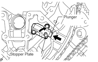
a.
A214604E04
1.354,1.927 1.438,1.927 1.438,1.927 1.615,1.26 false 1.792,1.208 2.042,0.594 2.042,0.594 2.188,0.594 false 0.354,1.823 1.448,2.156 1.094,0.333 10 true Stopper Plate 2.229,0.51 2.854,0.906 0.625,0.396 10 true Plunger

Move the stopper plate upward to release the lock, and push the plunger deep into the tensioner.
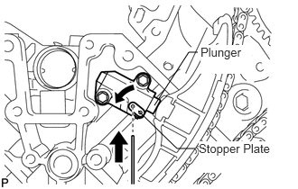

b.
A214605E04
1.594,1.281 2.042,1.719 2.042,1.719 2.25,1.719 false 1.781,1.219 2.177,0.604 2.177,0.604 2.281,0.604 false 2.292,1.635 3.188,2 0.896,0.365 10 true Stopper Plate 2.313,0.521 2.906,0.854 0.594,0.333 10 true Plunger

Move the stopper plate downward to set the lock, and insert a hexagon wrench into the stopper plate hole.
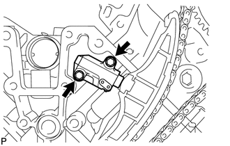

c.
A214606

Remove the 2 bolts, chain tensioner and gasket.


Hide 13559 4.REMOVE NO. 1 CHAIN TENSIONER SLIPPER LH
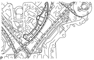
A214607

Hide 13561 5.REMOVE NO. 1 CHAIN VIBRATION DAMPER LH
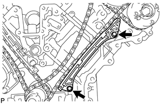
a.
A214608

Remove the 2 bolts and chain vibration damper.


Hide 13506 6.REMOVE NO. 1 CHAIN SUB-ASSEMBLY LH
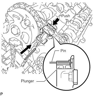
A214609E04
1.854,2.208 1.969,1.813 1.969,1.813 2.115,1.813 false 1.302,2.917 1.583,2.917 1.583,2.917 2.135,2.385 true 2.167,1.729 2.427,1.896 0.26,0.167 10 false Pin 0.75,2.813 1.313,2.99 0.563,0.177 10 false Plunger 2.198,0.479 2.583,0.677 0.385,0.198 10 true Push

a.

While pushing down the No. 3 chain tensioner, insert a pin of φ1.0 mm (0.0394 in.) into the hole to fix it in place.
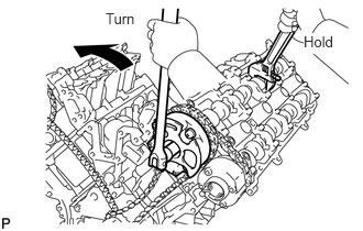

b.
A214610E04
1,0.094 1.344,0.281 0.344,0.188 10 false Turn 2.875,0.313 3.24,0.51 0.365,0.198 10 true Hold

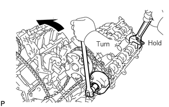
Hold the hexagonal portion of the camshaft with a wrench and loosen the bolt.

NOTICE:
·

Be careful not to damage the cylinder head with the wrench.

·

Do not disassemble the camshaft timing gear.


c.
A214611E04
1.958,0.813 2.333,1.073 0.375,0.26 10 true Turn 3.01,0.792 3.333,0.958 0.323,0.167 10 false Hold

Hold the hexagonal portion of the camshaft with a wrench and loosen the bolt.

NOTICE:

Be careful not to damage the cylinder head with the wrench.


d.

Remove the 2 bolts. Then with the No. 1 and No. 2 chains still connected to the gears, remove the camshaft timing gear, camshaft timing exhaust gear and crankshaft timing sprocket LH.


e.

Remove the No. 1 and No. 2 chains from the gears.


Hide 13560A 7.REMOVE NO. 3 CHAIN TENSIONER ASSEMBLY
A214612

a.

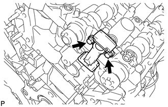
Remove the 2 bolts and chain tensioner.


Hide 8.REMOVE CAMSHAFT BEARING CAP LH

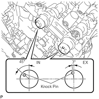
U151666E02
0.896,2.583 1.771,2.896 1.771,2.896 2.479,2.552 true 1.417,2.917 2.115,3.094 0.698,0.177 10 false Knock Pin 1.26,2.083 1.469,2.271 0.208,0.188 10 false IN 2.875,2.083 3.094,2.25 0.219,0.167 10 false EX 0.667,2.052 1.031,2.292 0.365,0.24 10 false 45° 2.5,2.063 2.708,2.271 0.208,0.208 10 false 3°

a.

Make sure that the knock pin of the camshaft is positioned as shown in the illustration.

b.
A163592E06
0.417,1.729 0.531,1.917 0.115,0.188 10 false 1 0.438,0.198 0.552,0.385 0.115,0.188 10 true 2 1.021,1.729 1.135,1.917 0.115,0.188 10 false 3 1.063,0.198 1.177,0.385 0.115,0.188 10 true 4 1.604,1.74 1.719,1.927 0.115,0.188 10 false 5 1.625,0.198 1.74,0.385 0.115,0.188 10 true 6 2.167,1.74 2.281,1.927 0.115,0.188 10 false 7 2.167,0.198 2.281,0.385 0.115,0.188 10 true 8 2.865,1.729 2.979,1.917 0.115,0.188 10 true 9 2.854,0.208 3.031,0.396 0.177,0.188 10 true 10

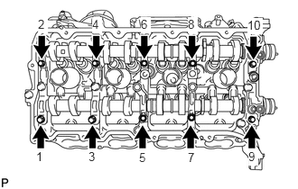
Uniformly loosen and remove the 10 bearing cap bolts in the sequence shown in the illustration.

c.
A163593E04
3.313,0.135 3.417,0.292 0.104,0.156 10 false 1 3.292,1.667 3.396,1.823 0.104,0.156 10 false 2 0.094,1.417 0.198,1.573 0.104,0.156 10 false 3 2.75,1.781 2.854,1.938 0.104,0.156 10 false 4 3.292,0.51 3.396,0.667 0.104,0.156 10 false 5 0.479,1.875 0.583,2.031 0.104,0.156 10 false 6 0.469,0 0.573,0.156 0.104,0.156 10 false 7 2.198,1.865 2.302,2.021 0.104,0.156 10 false 8 2.229,0 2.333,0.156 0.104,0.156 10 false 9 1.031,1.875 1.219,2.031 0.188,0.156 10 false 10 1.052,0.01 1.24,0.167 0.188,0.156 10 true 11 1.531,1.865 1.719,2.021 0.188,0.156 10 false 12 1.604,0 1.792,0.156 0.188,0.156 10 false 13 2.823,0.542 3.01,0.698 0.188,0.156 10 true 14 0.406,0.542 0.594,0.698 0.188,0.156 10 true 15 2.167,0.531 2.354,0.688 0.188,0.156 10 true 16 1.042,0.542 1.229,0.698 0.188,0.156 10 true 17 1.5,0.542 1.688,0.698 0.188,0.156 10 true 18

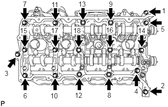
Uniformly loosen and remove the 18 bearing cap bolts in the sequence shown in the illustration.

NOTICE:

Uniformly loosen the bolts while keeping the camshaft level.


d.

Remove the 6 bearing caps.

HINT:

Arrange the removed parts in the correct order.


e.

Remove the No. 3 and No. 4 camshafts.


Hide 11104A 9.REMOVE CAMSHAFT HOUSING SUB-ASSEMBLY LH
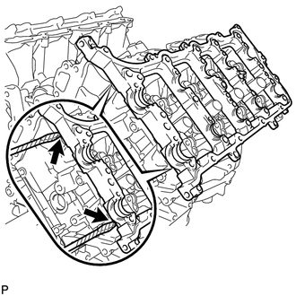
a.
A214624

Remove the camshaft housing by prying between the cylinder head and camshaft housing with a screwdriver.

HINT:

Tape the screwdriver tip before use.


NOTICE:

Be careful not to damage the contact surfaces of the cylinder head and camshaft housing.