TIRE AND WHEEL TIRE PRESSURE WARNING SYSTEM Tire Pressure Warning Reset Switch Circuit
DESCRIPTION
The tire pressure warning ECU enters the initialization mode and performs initialization automatically. Then it receives the signal from the tire pressure warning reset switch. If the ECU receives the signal, the tire pressure warning light blinks 3 times (1 second on, 1 second off).
WIRING DIAGRAM
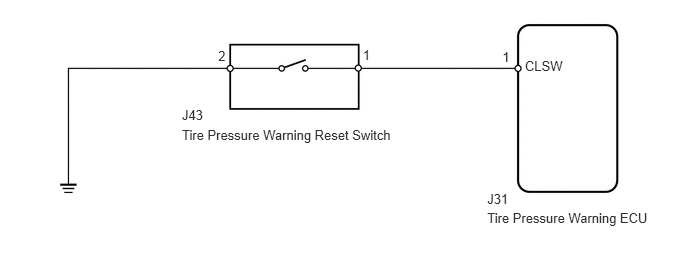
CAUTION / NOTICE / HINT
- NOTICE:
- ·
When replacing the tire pressure warning ECU, read the transmitter IDs stored in the old ECU using the Techstream and note down before removal.
·It is necessary to perform initialization (See page Drivetrain>TIRE AND WHEEL>TIRE PRESSURE WARNING SYSTEM>INITIALIZATION) after registration (See page Drivetrain>TIRE AND WHEEL>TIRE PRESSURE WARNING SYSTEM>REGISTRATION) of the transmitter IDs into the tire pressure warning ECU, after the ECU and/or tire pressure warning valve and transmitter has been replaced.
PROCEDURE
Perform the tire pressure warning reset switch test in Test Mode Procedure (See page Drivetrain>TIRE AND WHEEL>TIRE PRESSURE WARNING SYSTEM>TEST MODE PROCEDURE).
- OK:
Switch Condition Specified Condition Tire pressure warning reset switch on Tire pressure warning light turns on. Tire pressure warning reset switch off Tire pressure warning light blinks.
OK
(See pageGeneral>INTRODUCTION>HOW TO TROUBLESHOOT ECU CONTROLLED SYSTEMS>HOW TO PROCEED WITH TROUBLESHOOTING)
NG
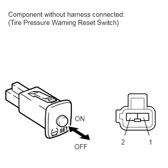
Remove the tire pressure warning reset switch (See page Drivetrain>TIRE AND WHEEL>TIRE PRESSURE WARNING RESET SWITCH>REMOVAL).
Measure the resistance according to the value(s) in the table below.
- Standard Resistance:
Tester Connection Switch Condition Specified Condition 1 - 2 ON (Switch is pressed and held) Below 1 Ω OFF (Switch is not pressed) 10 kΩ or higher
OK
NG
Disconnect the J43 reset switch connector.
Disconnect the J31 ECU connector.
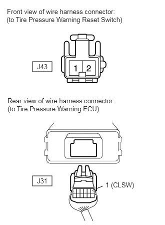
Measure the resistance according to the value(s) in the table below.
- Standard resistance:
Tester Connection Condition Specified Condition J31-1 (CLSW) - J43-1 Always Below 1 Ω J31-1 (CLSW) - Body ground Always 10 kΩ or higher J43-2 - Body ground Always Below 1 Ω
OK
NG