WF1AM TRANSFER TOUCH SELECT 2-4 AND HIGH-LOW SYSTEM P0560 System Voltage
DESCRIPTION
This DTC is detected when the 4 wheel drive control ECU, which monitors the B terminal voltage, determines that the standard voltage is not met and detects a B terminal system malfunction.
| DTC Code | DTC Detection Condition
1.
Diagnosis Condition 2.
Malfunction Status 3.
Malfunction Time 4.
Other |
Trouble Area |
|---|---|---|
| P0560 | 1.
The ignition switch is ON and the transfer position switch is operated 2.
Open circuit or short to ground in the B terminal system (B terminal voltage is below 9.5 V) 3.
1 second or more 4.
1 trip detection logic |
·
Battery ·
Charging system ·
Wire harness and connector ·
4 wheel drive control ECU |
WIRING DIAGRAM
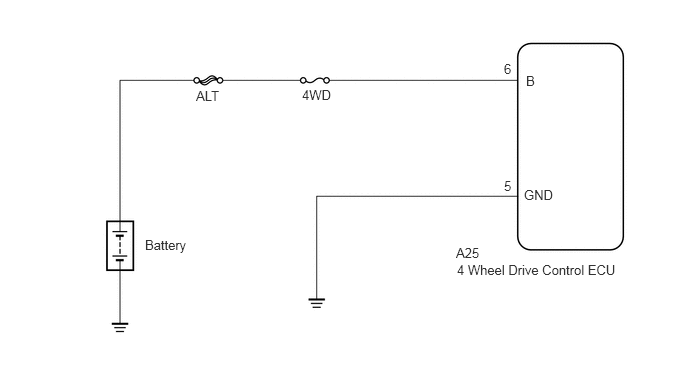
CAUTION / NOTICE / HINT
- NOTICE:
- ·
Inspect the fuses for circuits related to this system before performing the following inspection procedure.
·If only past DTCs are output, battery depletion may have occurred in the past.
PROCEDURE
Inspect the battery (3UR-FE: See page Engine / Hybrid System>3UR-FE CHARGING>CHARGING SYSTEM>ON-VEHICLE INSPECTION, 3UR-FBE: See page Engine / Hybrid System>3UR-FBE CHARGING>CHARGING SYSTEM>ON-VEHICLE INSPECTION, 1UR-FE: See page Engine / Hybrid System>1UR-FE CHARGING>CHARGING SYSTEM>ON-VEHICLE INSPECTION).
OK
NG
Check the battery terminals (3UR-FE: See page Engine / Hybrid System>3UR-FE CHARGING>CHARGING SYSTEM>ON-VEHICLE INSPECTION, 3UR-FBE: See page Engine / Hybrid System>3UR-FBE CHARGING>CHARGING SYSTEM>ON-VEHICLE INSPECTION, 1UR-FE: See page Engine / Hybrid System>1UR-FE CHARGING>CHARGING SYSTEM>ON-VEHICLE INSPECTION).
OK
NG
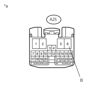
Disconnect the 4 wheel drive control ECU connector.
Measure the voltage according to the value(s) in the table below.
- Standard Voltage:
Tester Connection Condition Specified Condition A25-6 (B) - Body ground Always 11 to 14 V
| *a | Front view of wire harness connector
(to 4 Wheel Drive Control ECU) |
OK
NG
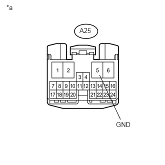
Disconnect the 4 wheel drive control ECU connector.
Measure the resistance according to the value(s) in the table below.
- Standard Resistance:
Tester Connection Condition Specified Condition A25-5 (GND) - Body ground Always Below 1 Ω
| *a | Front view of wire harness connector
(to 4 Wheel Drive Control ECU) |
OK
NG
Clear the DTCs (See page Drivetrain>WF1AM TRANSFER>TOUCH SELECT 2-4 AND HIGH-LOW SYSTEM>DTC CHECK / CLEAR).
Operate the transfer position switch.
Check if the same DTC is output (See page Drivetrain>WF1AM TRANSFER>TOUCH SELECT 2-4 AND HIGH-LOW SYSTEM>DTC CHECK / CLEAR).
| Result | Proceed to |
|---|---|
| DTC is output | A |
| DTC is not output | B |
A
B
(See pageGeneral>INTRODUCTION>HOW TO TROUBLESHOOT ECU CONTROLLED SYSTEMS>HOW TO PROCEED WITH TROUBLESHOOTING)