AB60F AUTOMATIC TRANSMISSION / TRANSAXLE OIL COOLER(w/ Trailer Towing System) INSTALLATION
PROCEDURE

 32907
1.INSTALL NO. 2 OIL COOLER TUBE
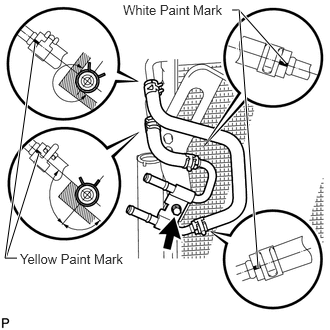
Install the No. 2 oil cooler inlet hose and No. 2 oil cooler outlet hose to the No. 2 oil cooler tube.
- NOTICE:
-
Make sure the paint marks and pinching portion of each clip are facing the directions shown in the illustration.
Install the No. 2 oil cooler tube together with the 2 oil cooler hoses with the bolt.
- Torque:
- 5.4 N*m (55 kgf*cm, 48 in.*lbf)
Connect the No. 2 oil cooler inlet hose and No. 2 oil cooler outlet hose to the cooler condenser.
- NOTICE:
- ·
Make sure the paint marks are facing the directions shown in the illustration.
·Make sure the pinching portion of each clip is not in the hatched areas shown in the illustration.
88350
2.INSTALL COOLER CONDENSER ASSEMBLY (AIR COOLED OIL COOLER)
Install the cooler condenser (See page Vehicle Interior>AIR CONDITIONING>CONDENSER>INSTALLATION).
32907A
3.INSTALL OIL COOLER TUBE
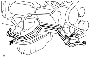
Install the oil cooler tube with the 2 bolts.
- Torque:
- 14 N*m (143 kgf*cm, 10 ft.*lbf)
32930
4.INSTALL OIL COOLER ACCESSORY ASSEMBLY
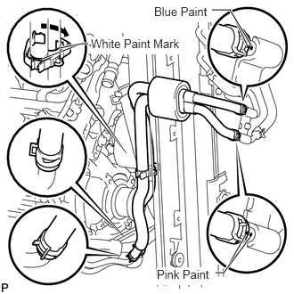
Install the oil cooler accessory assembly to the oil cooler tube, and then pass the 2 hoses through the No. 1 flexible hose clamp and close the clamp as shown in the illustration.
Connect the 2 hoses to the No. 2 oil cooler tube.
- NOTICE:
- ·
When connecting the hoses to the tube, support the tube by hand and be careful to prevent the tube from being deformed.
·Make sure the paint marks and pinching portion of each clip are facing the directions shown in the illustration.
32941
5.INSTALL NO. 1 OIL COOLER INLET HOSE AND NO. 1 OIL COOLER OUTLET HOSE
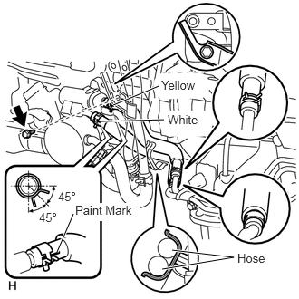
Connect the No. 1 oil cooler inlet hose and No. 1 oil cooler outlet hose to the oil cooler tube.
Connect the 2 hoses to the transmission oil thermostat to install them.
- NOTICE:
- ·
When connecting the hoses to the tube, support the tube by hand and be careful to prevent the tube from being deformed.
·Make sure the paint marks and pinching portion of each clip are facing the directions shown in the illustration.
Install the bolt to fix the water by-pass pipe in place.
- Torque:
- 18 N*m (184 kgf*cm, 13 ft.*lbf)
6.ADD AUTOMATIC TRANSMISSION FLUID
Add automatic transmission fluid (See page Drivetrain>AB60E AUTOMATIC TRANSMISSION / TRANSAXLE>AUTOMATIC TRANSMISSION FLUID>ADJUSTMENT).
7.INSTALL FRONT BUMPER ASSEMBLY
Install the front bumper (See page Vehicle Interior>EXTERIOR>FRONT BUMPER>INSTALLATION).