A760E AUTOMATIC TRANSMISSION / TRANSAXLE OIL COOLER INSTALLATION
PROCEDURE

 33490F
1.INSTALL TRANSMISSION OIL COOLER ASSEMBLY
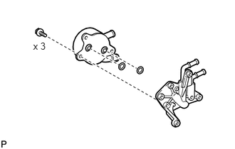
Coat 2 new O-rings with ATF and install them to the grooves of the transmission oil cooler.
Install the transmission oil cooler to the transmission oil cooler spacer with the 3 bolts.
- Torque:
- 14 N*m (143 kgf*cm, 10 ft.*lbf)
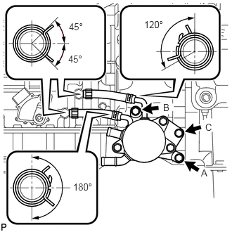
Install the 2 No. 1 transmission oil cooler hoses to the transmission oil cooler spacer.
- NOTICE:
-
Make sure the pinching portion of each clip is facing the direction shown in the illustration.
Connect the 2 No. 1 transmission oil cooler hoses to the transmission.
- NOTICE:
-
Make sure the pinching portion of each clip is facing the direction shown in the illustration.
Temporarily install the transmission oil cooler together with the transmission oil cooler spacer with bolt C. Temporarily install bolt A and bolt B. Tighten the bolts in alphabetical order.
- Torque:
- 21 N*m (214 kgf*cm, 15 ft.*lbf)
16268
2.CONNECT WATER BY-PASS PIPE ASSEMBLY
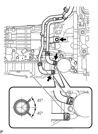
Connect the 2 water by-pass hoses to the transmission oil cooler and connect the water by-pass pipe with the bolt.
- Torque:
- 18 N*m (184 kgf*cm, 13 ft.*lbf)
| *a | Yellow Paint Mark |
| *b | White Paint Mark |
- NOTICE:
-
Make sure the paint marks and pinching portion of each clip are facing the directions shown in the illustration.
17410
3.INSTALL FRONT EXHAUST PIPE ASSEMBLY
4.ADD ENGINE COOLANT
5.ADJUST AUTOMATIC TRANSMISSION FLUID LEVEL
6.INSPECT FOR COOLANT LEAK
7.INSPECT FOR EXHAUST GAS LEAK
8.INSPECT FOR AUTOMATIC TRANSMISSION FLUID LEAK