1UR-FE EXHAUST EXHAUST MANIFOLD INSTALLATION
CAUTION / NOTICE / HINT
- HINT:
-
If an exhaust gas leak has been repaired, perform an inspection following the repair (See page Engine / Hybrid System>1UR-FE ENGINE CONTROL>SFI SYSTEM>INITIALIZATION).
PROCEDURE

 17104
1.INSTALL EXHAUST MANIFOLD SUB-ASSEMBLY RH
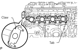
Install a new gasket to the cylinder head and a new gasket to the No. 3 air tube.
- HINT:
- ·
Install the exhaust manifold gasket with the gasket tab facing toward the front of the engine.
·Install the air tube gasket with the gasket's claws facing the tube.
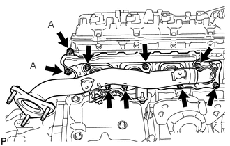
Temporarily install the exhaust manifold with 9 new nuts, and then uniformly tighten the 7 nuts that are not labeled A. Then tighten the 2 nuts labeled A in the illustration.
- Torque:
- for nut A : 10 N*m (102 kgf*cm, 7 ft.*lbf)
- except nut A : 21 N*m (214 kgf*cm, 15 ft.*lbf)
17167
2.INSTALL NO. 1 EXHAUST MANIFOLD HEAT INSULATOR
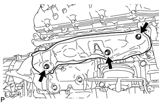
Install the heat insulator with the 3 bolts.
- Torque:
- 10 N*m (102 kgf*cm, 7 ft.*lbf)
17105
3.INSTALL EXHAUST MANIFOLD SUB-ASSEMBLY LH
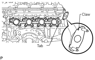
Install a new gasket to the cylinder head and a new gasket to the No. 4 air tube.
- HINT:
- ·
Install the exhaust manifold gasket with the gasket tab facing toward the rear of the engine.
·Install the air tube gasket with the gasket's claws facing the tube.
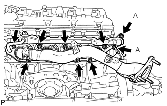
Temporarily install the exhaust manifold with 9 new nuts, and then uniformly tighten the 7 nuts that are not labeled A. Then tighten the 2 nuts labeled A in the illustration.
- Torque:
- for nut A : 10 N*m (102 kgf*cm, 7 ft.*lbf)
- except nut A : 21 N*m (214 kgf*cm, 15 ft.*lbf)
17168
4.INSTALL NO. 2 EXHAUST MANIFOLD HEAT INSULATOR
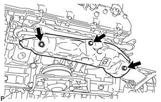
Install the heat insulator with the 3 bolts.
- Torque:
- 10 N*m (102 kgf*cm, 7 ft.*lbf)
25601
5.INSTALL NO. 1 EGR PIPE SUB-ASSEMBLY
Install 2 new gaskets.
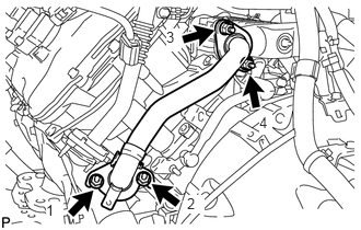
Install the EGR pipe with the 4 nuts, and tighten the nuts in the sequence shown in the illustration.
- Torque:
- 21 N*m (214 kgf*cm, 15 ft.*lbf)
58155
6.INSTALL FRONT NO. 3 FLOOR HEAT INSULATOR
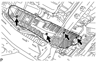
Install the front floor heat insulator with the 4 bolts.
- Torque:
- 5.5 N*m (56 kgf*cm, 49 in.*lbf)
58156
7.INSTALL FRONT NO. 4 FLOOR HEAT INSULATOR
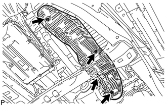
Install the front floor heat insulator with the 4 bolts.
- Torque:
- 5.5 N*m (56 kgf*cm, 49 in.*lbf)
37140
8.INSTALL FRONT PROPELLER SHAFT ASSEMBLY (for 4WD)
9.INSTALL EXHAUST PIPE ASSEMBLY
88320
10.CONNECT COOLER COMPRESSOR ASSEMBLY
27020
11.INSTALL GENERATOR ASSEMBLY
11452
12.INSTALL ENGINE OIL LEVEL DIPSTICK GUIDE
Apply a light coat of engine oil to a new O-ring.
Install the O-ring to the dipstick guide.
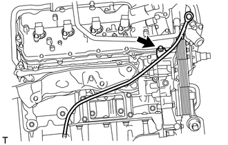
Install the dipstick guide with the bolt.
- Torque:
- 10 N*m (102 kgf*cm, 7 ft.*lbf)
Install the dipstick.
17111
13.INSTALL INTAKE MANIFOLD
14.INSPECT FOR EXHAUST GAS LEAK
- HINT:
-
If an exhaust gas leak has been repaired, perform an inspection following the repair (See page Engine / Hybrid System>1UR-FE ENGINE CONTROL>SFI SYSTEM>INITIALIZATION).
If gas is leaking, tighten the areas necessary to stop the leak. Replace damaged parts as necessary.
53739A
15.INSTALL FRONT FENDER APRON SEAL REAR LH
Install the fender apron seal with the 5 clips.
53737B
16.INSTALL FRONT FENDER APRON SEAL LH
Install the fender apron seal with the 6 clips.
53736A
17.INSTALL FRONT FENDER APRON SEAL REAR RH
Install the fender apron seal with the 5 clips.
53736
18.INSTALL FRONT FENDER APRON SEAL RH
Install the fender apron seal with the 6 clips.