SUPPLEMENTAL RESTRAINT SYSTEMS AIRBAG SYSTEM SRS Warning Light does not Come ON
DESCRIPTION
Refer to the "SRS Warning Light Remains ON" (See page Vehicle Interior>SUPPLEMENTAL RESTRAINT SYSTEMS>AIRBAG SYSTEM>SRS Warning Light Remains ON).
WIRING DIAGRAM
Refer to the "SRS Warning Light Remains ON" (See page Vehicle Interior>SUPPLEMENTAL RESTRAINT SYSTEMS>AIRBAG SYSTEM>SRS Warning Light Remains ON).
CAUTION / NOTICE / HINT
- NOTICE:
- ·
After turning the ignition switch off, waiting time may be required before disconnecting the cable from the negative (-) battery terminal. Therefore, make sure to read the disconnecting the cable from the negative (-) battery terminal notices before proceeding with work (See page General>INTRODUCTION>REPAIR INSTRUCTION>PRECAUTION).
·When disconnecting the cable from the negative (-) battery terminal while performing repairs, some systems need to be initialized after the cable is reconnected (See page General>INTRODUCTION>REPAIR INSTRUCTION>INITIALIZATION).
PROCEDURE
Measure the voltage of the battery.
- Standard voltage:
11 to 14 V
OK
NG
Turn the ignition switch off.
Disconnect the negative (-) terminal cable from the battery, and wait for at least 90 seconds.
Check that the connectors are properly connected to the combination meter.
- OK:
The connectors are properly connected.
OK
NG
Turn the ignition switch off.
Disconnect the negative (-) terminal cable from the battery, and wait for at least 90 seconds.
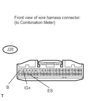
Disconnect the J28 combination meter connector.
Connect the negative (-) terminal cable to the battery, and wait for at least 2 seconds.
Turn the ignition switch to ON.
Measure the voltage and resistance according to the value(s) in the table below.
- Standard voltage:
Tester Connection Switch Condition Specified Condition J28-1 (B) - J28-24 (ES) Ignition switch ON 11 to 14 V J28-2 (IG+) - J28-24 (ES)
- Standard resistance:
Tester Connection Condition Specified Condition J28-24 (ES) - Body ground Always Below 1 Ω
OK
NG
Turn the ignition switch off.
Disconnect the negative (-) terminal cable from the battery, and wait for at least 90 seconds.
Connect the connector to the combination meter.
Connect the negative (-) terminal cable to the battery, and wait for at least 2 seconds.
Turn the ignition switch to ON.
Check the SRS warning light condition.
- OK:
After the primary check period, SRS warning light goes off for approximately 10 seconds and remains on.
| Result | Proceed to |
|---|---|
| NG | A |
| OK (for Column Shift Type) | B |
| OK (for Floor Shift Type) | C |
- HINT:
-
The primary check period is approximately 6 seconds after the ignition switch is turned ON.
C
A
(See pageVehicle Interior>METER / GAUGE / DISPLAY>METER / GAUGE SYSTEM>DIAGNOSTIC TROUBLE CODE CHART)
B