AUDIO / VIDEO STEREO COMPONENT AMPLIFIER INSTALLATION
PROCEDURE

 86280
1.INSTALL STEREO COMPONENT AMPLIFIER ASSEMBLY
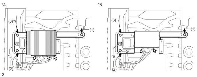
| *A | for 12 Speakers | *B | except 12 Speakers |
| *a | Guide | - | - |
Attach the guide to install the stereo component amplifier assembly.
Install the 3 bolts.
- Torque:
- 8.5 N*m (87 kgf*cm, 75 in.*lbf)
- HINT:
-
Tighten the bolts in the order shown in the illustration.
for 12 Speakers:
Connect the 3 connectors.
except 12 Speakers:
Connect the 2 connectors.
86183D
2.INSTALL AUDIO AMPLIFIER COVER
Attach the 3 clips to install the audio amplifier cover.
3.INSTALL FRONT SEAT ASSEMBLY RH
for Manual Seat:
(See page Vehicle Interior>SEAT>FRONT SEAT ASSEMBLY(for Manual Seat)>INSTALLATION)
for Power Seat:
(See page Vehicle Interior>SEAT>FRONT SEAT ASSEMBLY(for Power Seat)>INSTALLATION)
4.CONNECT CABLE TO NEGATIVE BATTERY TERMINAL
- NOTICE:
-
When disconnecting the cable, some systems need to be initialized after the cable is reconnected (See page General>INTRODUCTION>REPAIR INSTRUCTION>INITIALIZATION).