BRAKE CONTROL / DYNAMIC CONTROL SYSTEMS VEHICLE STABILITY CONTROL SYSTEM C1241/41 Low Battery Positive Voltage or Abnormally High Battery Positive Voltage
DESCRIPTION
When there is an abnormality in the power supply circuit of the VSC actuator (skid control ECU), the skid control ECU sets a DTC and the operation is prohibited by the fail-safe function. This DTC is set when the voltage supplied to terminal +BS is outside the DTC detection threshold due to abnormalities of the battery, power source circuits or charging circuits such as the alternator circuit.
The fail-safe function is canceled when the voltage to terminal +BS returns to normal.
- HINT:
-
If the vehicle speed is 20 km/h (12 mph) or less when the battery voltage is low, the ABS warning light and SLIP indicator light illuminate. However, a DTC will not be output.
| DTC Code | DTC Detection Condition | Trouble Area |
|---|---|---|
| C1241/41 | When any of following conditions detected:
1.
+BS terminal voltage 18 V or more (momentary occurrence included). 2.
At vehicle speed 20 km/h (12 mph) or more, +BS terminal voltage 9.7 V or less for 0.21 seconds or more. 3.
At vehicle speed 20 km/h (12 mph) or more, +BS terminal voltage 8.5 V or less (momentary occurrence included). |
·
Battery ·
Charging system ·
Power source circuit ·
Skid control ECU |
WIRING DIAGRAM
Refer to DTC C0278/11 (See page Brake>BRAKE CONTROL / DYNAMIC CONTROL SYSTEMS>VEHICLE STABILITY CONTROL SYSTEM>C0278/11).
CAUTION / NOTICE / HINT
- NOTICE:
-
When replacing the VSC actuator assembly, perform zero point calibration (See page Brake>BRAKE CONTROL / DYNAMIC CONTROL SYSTEMS>VEHICLE STABILITY CONTROL SYSTEM>CALIBRATION).
PROCEDURE
Check the battery voltage.
- Standard voltage:
11 to 14 V
| Result | Proceed to |
|---|---|
| OK | A |
| NG (for 1UR-FE) | B |
| NG (for 3UR-FE) | C |
| NG (for 3UR-FBE) | D |
A
B
C
D
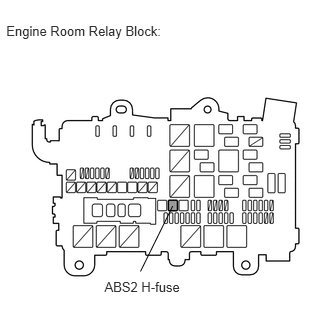
Remove the ABS2 H-fuse from the engine room relay block.
Measure the resistance according to the value(s) in the table below.
- Standard Resistance:
Tester Connection Condition Specified Condition ABS2 H-fuse Always Below 1 Ω
OK
NG
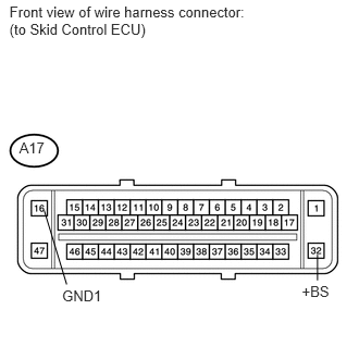
Disconnect the A17 ECU connector.
Measure the voltage according to the value(s) in the table below.
- Standard Voltage:
Tester Connection Condition Specified Condition A17-32 (+BS) - Body ground Always 11 to 14 V
Measure the resistance according to the value(s) in the table below.
- Standard Resistance:
Tester Connection Condition Specified Condition A17-16 (GND1) - Body ground Always Below 1 Ω
OK
NG
Clear the DTCs (See page Brake>BRAKE CONTROL / DYNAMIC CONTROL SYSTEMS>VEHICLE STABILITY CONTROL SYSTEM>DTC CHECK / CLEAR).
Start the engine.
Check if the same DTCs are output (See page Brake>BRAKE CONTROL / DYNAMIC CONTROL SYSTEMS>VEHICLE STABILITY CONTROL SYSTEM>DTC CHECK / CLEAR).
| Result | Proceed to |
|---|---|
| DTC is output | A |
| DTC is not output | B |
A
B
(See pageGeneral>INTRODUCTION>HOW TO TROUBLESHOOT ECU CONTROLLED SYSTEMS>HOW TO PROCEED WITH TROUBLESHOOTING)