Home › Brake › BRAKE CONTROL / DYNAMIC CONTROL SYSTEMS › VEHICLE STABILITY CONTROL SYSTEM
RM27M0U _54 Brake _049153 BRAKE CONTROL / DYNAMIC CONTROL SYSTEMS _0234401 VEHICLE STABILITY CONTROL SYSTEM C

BRAKE CONTROL / DYNAMIC CONTROL SYSTEMS  VEHICLE STABILITY CONTROL SYSTEM  C1249/49  Open in Stop Light Switch Circuit  


DESCRIPTION

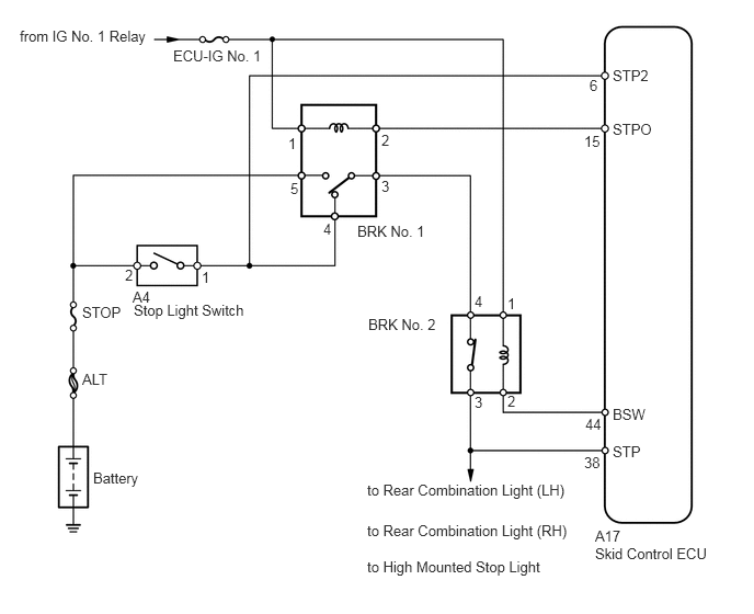
The skid control ECU detects the brake operating conditions through a signal transmitted by the stop light switch. The skid control ECU incorporates an open circuit detection circuit.

DTC Code DTC Detection Condition Trouble Area
C1249/49 When one of following conditions is met:
1.

When voltage of STP2 pin is detected to be outside range of 1.4 to 2.2 V for 2.5 second.

2.

When pressure sensor signal indicates pressure increase, but stop light switch signal does not change.

3.

While driving at speed of 20 km/h (12 mph) or more, stop light switch is ON for more than 6 minutes.

4.

While vehicle is accelerated to higher than 40 km/h (24.9 mph) and then decelerated to less than 3 km/h (1.9 mph), stop light switch signal change from OFF to ON is not detected (4 trip detection logic).


·

ECU-IG1 NO. 1 fuse

·

STOP fuse

·

Stop light control relay

·

Stop light switch

·

Stop light switch circuit

·

VSC actuator assembly


WIRING DIAGRAM

C162016E13
0.188,0.26 1.51,0.427 1.323,0.167 10 false from IG No. 1 Relay 1.646,0.448 2.563,0.615 0.917,0.167 10 false ECU-IG No. 1 5.823,0.635 6.24,0.802 0.417,0.167 10 false STP2 5.604,0.729 5.802,0.896 0.198,0.167 10 false 6 4.51,3.74 4.615,3.906 0.104,0.167 10 false 3 4.51,2.781 4.615,2.948 0.104,0.167 10 false 4 4.823,3.729 4.927,3.896 0.104,0.167 10 false 2 5.552,1.26 5.771,1.427 0.219,0.167 10 false 15 4.823,2.802 4.927,2.969 0.104,0.167 10 false 1 1.188,2.531 1.292,2.698 0.104,0.167 10 false 2 1.917,2.552 2.021,2.719 0.104,0.167 10 false 1 3.625,1.688 3.729,1.854 0.104,0.167 10 false 3 3.073,2.094 3.177,2.26 0.104,0.167 10 false 4 2.76,1.708 2.865,1.875 0.104,0.167 10 false 5 3.625,1.25 3.729,1.417 0.104,0.167 10 false 2 2.74,1.281 2.844,1.448 0.104,0.167 10 false 1 5.823,1.146 6.24,1.313 0.417,0.167 10 false STPO 5.823,3.854 6.24,4.021 0.417,0.167 10 false BSW 5.563,3.948 5.771,4.115 0.208,0.167 10 false 44 5.552,4.313 5.76,4.479 0.208,0.167 10 false 38 5.823,4.208 6.24,4.375 0.417,0.167 10 false STP 1.271,2.865 2.49,3.094 1.219,0.229 10 false Stop Light Switch 3.396,2.115 4.583,2.49 1.188,0.375 10 false BRK No. 1 3.5,3 4.25,3.229 0.75,0.229 10 false BRK No. 2 3.49,4.573 5.552,4.771 2.063,0.198 10 false to Rear Combination Light (LH) 3.49,4.958 5.552,5.156 2.063,0.198 10 false to Rear Combination Light (RH) 5.656,5.177 6.813,5.375 1.156,0.198 10 false Skid Control ECU 5.656,5.01 5.979,5.208 0.323,0.198 10 false A17 3.49,5.302 5.344,5.5 1.854,0.198 10 false to High Mounted Stop Light 0.885,4.458 1.385,4.625 0.5,0.167 10 false Battery 0.781,3.521 1.094,3.688 0.313,0.167 10 false ALT 0.781,2.885 1.281,3.052 0.5,0.167 10 false STOP 1.26,2.74 1.5,2.906 0.24,0.167 10 false A4

CAUTION / NOTICE / HINT

NOTICE:

When replacing the VSC actuator assembly, perform zero point calibration (See page Brake>BRAKE CONTROL / DYNAMIC CONTROL SYSTEMS>VEHICLE STABILITY CONTROL SYSTEM>CALIBRATION).


PROCEDURE
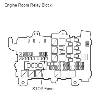
1.INSPECT FUSE (STOP)
a.
C160102E02
0.148,0.083 1.869,0.267 1.721,0.184 10 Engine Room Relay Block: 1.079,2.872 1.891,3.074 0.812,0.202 10 STOP Fuse 1.529,1.782 1.369,2.845 false

Remove the STOP fuse from the engine room relay block.


b.

Measure the resistance according to the value(s) in the table below.

Standard Resistance:
Tester Connection Condition Specified Condition
STOP fuse Always Below 1 Ω


OK

2.INSPECT STOP LIGHT CONTROL RELAY (BRK NO. 1, BRK NO. 2)

NG

CHECK FOR SHORTS IN ALL HARNESSES AND CONNECTORS CONNECTED TO FUSE AND REPLACE FUSE

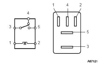
2.INSPECT STOP LIGHT CONTROL RELAY (BRK NO. 1, BRK NO. 2)
a.
A087121E36
2.354,0.604 2.354,0.292 false 2.49,1.115 2.958,1.115 false 2.49,1.615 2.958,1.615 false 2.042,0.604 1.865,0.292 false 2.635,0.604 2.813,0.292 false 0.313,1.396 0.51,1.604 0.198,0.208 10 false 1 1.813,0.083 2.01,0.292 0.198,0.208 10 false 1 1.313,1.396 1.51,1.604 0.198,0.208 10 false 2 2.76,0.083 2.958,0.292 0.198,0.208 10 false 2 0.313,0.844 0.51,1.052 0.198,0.208 10 false 3 3.01,1.531 3.208,1.74 0.198,0.208 10 false 3 0.938,0.365 1.135,0.573 0.198,0.208 10 false 4 2.302,0.083 2.5,0.292 0.198,0.208 10 false 4 1.313,0.844 1.51,1.052 0.198,0.208 10 false 5 3.01,1.021 3.208,1.229 0.198,0.208 10 false 5

Remove the stop light control relays (BRK NO. 1 and BRK NO. 2) from the engine room relay block.


b.

Measure the resistance according to the value(s) in the table below.

Standard Resistance:
for BRK NO. 1:
Tester Connection Condition Specified Condition
3 - 4 When battery voltage is not applied to terminals 1 and 2 Below 1 Ω
3 - 5 When battery voltage is not applied to terminals 1 and 2 10 kΩ or higher
3 - 4 When battery voltage is applied to terminals 1 and 2 10 kΩ or higher
3 - 5 When battery voltage is applied to terminals 1 and 2 Below 1 Ω

for BRK NO. 2:
Tester Connection Condition Specified Condition
3 - 4 When battery voltage is not applied to terminals 1 and 2 Below 1 Ω
When battery voltage is applied to terminals 1 and 2 10 kΩ or higher


OK

3.INSPECT STOP LIGHT SWITCH ASSEMBLY

NG

REPLACE STOP LIGHT CONTROL RELAY

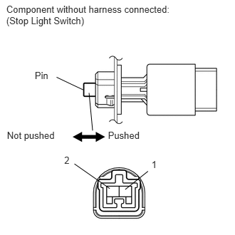
3.INSPECT STOP LIGHT SWITCH ASSEMBLY
a.
C108891E13
0.509,1.025 0.801,1.227 0.292,0.202 10 Pin 0.102,1.892 1.010,2.094 0.909,0.202 10 Not pushed 1.58,1.892 2.489,2.094 0.909,0.202 10 Pushed 0.94,2.26 1.241,2.462 0.300,0.202 10 2 2.216,2.322 2.575,2.553 0.359,0.231 10 1 1.216,1.313 1.01,1.216 1.01,1.216 0.827,1.129 false 1.302,1.359 1.354,1.909 false 1.831,2.771 2.164,2.505 false 1.605,2.758 1.088,2.397 false 0.092,0.053 2.690,0.413 2.598,0.360 10 Component without harness connected: (Stop Light Switch)

Disconnect the A4 switch connector.


b.

Measure the resistance according to the value(s) in the table below.

Standard Resistance:
Tester Connection Switch Condition Specified Condition
1 - 2 Pin not pushed Below 1 Ω
Pin pushed 10 kΩ or higher


OK

4.CHECK HARNESS AND CONNECTOR (BATTERY - SKID CONTROL ECU)

NG

REPLACE STOP LIGHT SWITCH ASSEMBLY

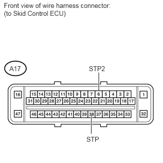
4.CHECK HARNESS AND CONNECTOR (BATTERY - SKID CONTROL ECU)
a.
U152476E02
2.083,1.531 2.083,1.906 true 1.927,2.438 1.927,2.823 true 0.083,0.031 2.438,0.344 2.354,0.313 10 false Front view of wire harness connector: (to Skid Control ECU) 1.823,2.854 2.135,3.01 0.313,0.156 10 false STP 1.875,1.365 2.302,1.521 0.427,0.156 10 false STP2 0.198,1.365 0.521,1.542 0.323,0.177 10 false A17

Disconnect the A17 ECU connector.


b.

Measure the voltage according to the value(s) in the table below.

Standard Voltage:
Tester Connection Condition Specified Condition
A17-6 (STP2) - Body ground Brake pedal depressed 8 to 14 V
A17-6 (STP2) - Body ground Brake pedal released Below 4.0 V
A17-38 (STP) - Body ground Brake pedal depressed 8 to 14 V
A17-38 (STP) - Body ground Brake pedal released Below 4.0 V


OK

NG

REPAIR OR REPLACE HARNESS OR CONNECTOR