Home › Brake › BRAKE CONTROL / DYNAMIC CONTROL SYSTEMS › VEHICLE STABILITY CONTROL SYSTEM
RM27M0U _54 Brake _049153 BRAKE CONTROL / DYNAMIC CONTROL SYSTEMS _0234401 VEHICLE STABILITY CONTROL SYSTEM J

BRAKE CONTROL / DYNAMIC CONTROL SYSTEMS  VEHICLE STABILITY CONTROL SYSTEM  TS and CG Terminal Circuit  


DESCRIPTION

In the sensor check mode, a malfunction of the speed sensor that cannot be detected when the vehicle is stopped can be detected while driving.

Transition to the sensor check mode can be performed by connecting terminals TS and CG of the DLC3 and turning the ignition switch from off to ON.

WIRING DIAGRAM
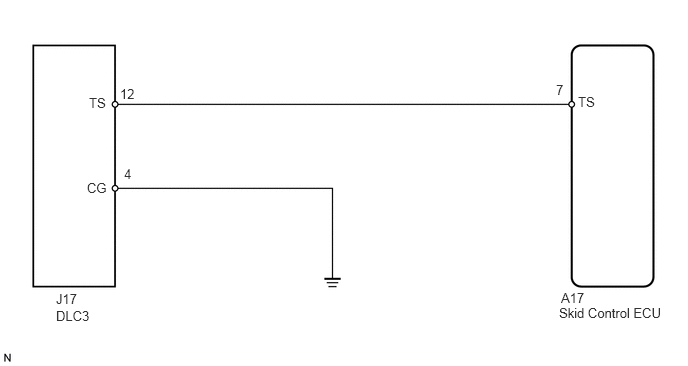
C140173E15
5.844,3.021 6.281,3.208 0.438,0.188 10 false A17 0.927,0.99 1.156,1.198 0.229,0.208 10 false TS 0.906,1.875 1.229,2.083 0.323,0.208 10 false CG 6.021,0.979 6.25,1.188 0.229,0.208 10 false TS 5.792,0.854 6.021,1.042 0.229,0.188 10 false 7 1.25,0.896 1.469,1.042 0.219,0.146 10 false 12 1.292,1.729 1.5,1.885 0.208,0.156 10 false 4 5.823,3.177 6.979,3.385 1.156,0.208 10 false Skid Control ECU 0.583,3.031 0.99,3.188 0.406,0.156 10 false J17 0.583,3.208 0.969,3.385 0.385,0.177 10 false DLC3

CAUTION / NOTICE / HINT

NOTICE:

When replacing the VSC actuator assembly, perform initialization of linear solenoid valve calibration (See page Brake>BRAKE CONTROL / DYNAMIC CONTROL SYSTEMS>VEHICLE STABILITY CONTROL SYSTEM>CALIBRATION).


PROCEDURE
1.CHECK HARNESS AND CONNECTOR (SKID CONTROL ECU - DLC3)
a.
C353056E01
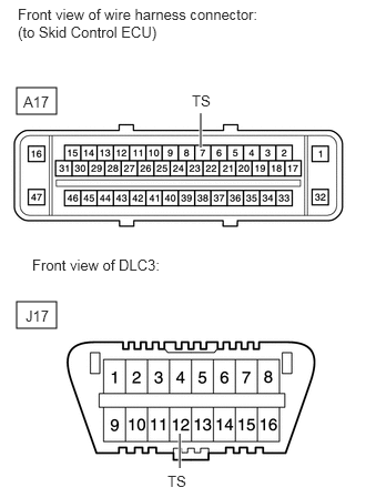
0.156,0.823 0.531,1.073 0.375,0.25 0.156,2.833 0.531,3.083 0.375,0.25 1.885,1.385 1.885,1.063 true 1.688,4.396 1.688,4.073 true 0.167,0.052 2.458,0.438 2.292,0.385 10 false Front view of wire harness connector: (to Skid Control ECU) 0.219,0.875 0.531,1.052 0.313,0.177 10 false A17 0.24,2.885 0.552,3.063 0.313,0.177 10 false J17 0.302,2.406 1.615,2.604 1.313,0.198 10 false Front view of DLC3: 1.802,0.865 2.135,1.031 0.333,0.167 10 false TS 1.573,4.438 1.906,4.604 0.333,0.167 10 false TS

Turn the ignition switch off.


b.

Disconnect the A17 ECU connector.


c.

Measure the resistance according to the value(s) in the table below.

Standard Resistance:
Tester Connection Condition Specified Condition
A17-7 (TS) - J17-12 (TS) Always Below 1 Ω


OK

2.CHECK HARNESS AND CONNECTOR (DLC3 - BODY GROUND)

NG

REPAIR OR REPLACE HARNESS OR CONNECTOR

2.CHECK HARNESS AND CONNECTOR (DLC3 - BODY GROUND)
a.
U152947E01
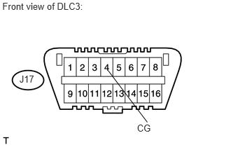
0.035,0.015 1.372,0.206 1.336,0.191 10 Front view of DLC3: 2.039,1.821 2.334,1.977 0.295,0.156 10 CG 1.608,1.048 2.192,1.819 false 0.289,1.092 0.580,1.252 0.290,0.161 10 J17

Measure the resistance according to the value(s) in the table below.

Standard Resistance:
Tester Connection Condition Specified Condition
J17-4 (CG) - Body ground Always Below 1 Ω


OK

3.CHECK HARNESS AND CONNECTOR (DLC3 - BODY GROUND)

NG

REPAIR OR REPLACE HARNESS OR CONNECTOR

3.CHECK HARNESS AND CONNECTOR (DLC3 - BODY GROUND)
a.
U152949E01
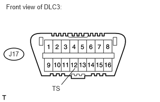
1.117,1.815 1.351,1.965 0.234,0.150 10 TS 1.612,1.462 1.319,1.815 false 0.131,0.065 1.460,0.302 1.329,0.237 10 Front view of DLC3: 0.188,1.068 0.501,1.295 0.313,0.227 10 J17

Measure the resistance according to the value(s) in the table below.

Standard Resistance:
Tester Connection Condition Specified Condition
J17-12 (TS) - Body ground Always 10 kΩ or higher


HINT:

If troubleshooting has been carried out according to the Problem Symptoms Table, refer back to the table and proceed to the next step before replacing the part (See page Brake>BRAKE CONTROL / DYNAMIC CONTROL SYSTEMS>VEHICLE STABILITY CONTROL SYSTEM>PROBLEM SYMPTOMS TABLE).


OK

NG

REPAIR OR REPLACE HARNESS OR CONNECTOR