Home › Vehicle Interior › ENGINE IMMOBILISER › ENGINE IMMOBILISER SYSTEM
RM27M0U _58 Vehicle Interior _049156 ENGINE IMMOBILISER _0234432 ENGINE IMMOBILISER SYSTEM C

ENGINE IMMOBILISER  ENGINE IMMOBILISER SYSTEM  B2796  No Communication in Immobiliser System  B2798  Communication Malfunction No. 2  


DESCRIPTION

·

DTC B2796 is output when a key is inserted into the ignition key cylinder but no communication occurs between the key and transponder key ECU.

·

DTC B2798 is output when a key is inserted into the ignition key cylinder but a communication error occurs between the key and transponder key ECU.


DTC Code DTC Detection Condition Trouble Area
B2796 The key code cannot be transmitted
·

Key

·

Harness or connector

·

Transponder key ECU

·

Transponder key amplifier


B2798 Key code identification cannot be completed within the specified time Key

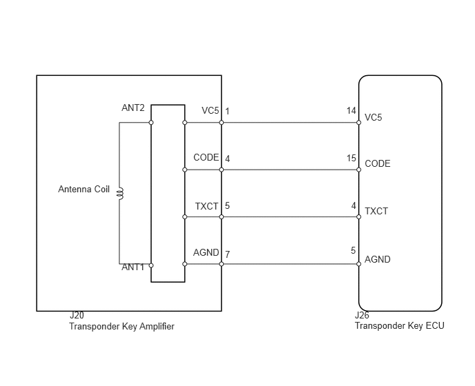
WIRING DIAGRAM

B121682E15
1.04,4.843 2.839,5.075 1.798,0.232 10 Transponder Key Amplifier 0.878,2.774 1.741,2.964 0.863,0.190 10 Antenna Coil 5.351,4.83 6.829,5.062 1.478,0.232 10 Transponder Key ECU 5.502,1.685 5.847,1.860 0.345,0.175 10 VC5 5.502,2.388 5.991,2.563 0.489,0.175 10 CODE 5.502,3.108 6.013,3.282 0.510,0.175 10 TXCT 5.502,3.831 6.007,4.006 0.505,0.175 10 AGND 3.043,1.588 3.388,1.763 0.345,0.175 10 VC5 1.836,1.546 2.244,1.721 0.408,0.175 10 ANT2 1.836,3.945 2.244,4.120 0.408,0.175 10 ANT1 2.916,2.291 3.405,2.466 0.489,0.175 10 CODE 2.916,3.734 3.421,3.909 0.505,0.175 10 AGND 5.223,1.588 5.577,1.924 0.355,0.336 10 14 5.224,2.306 5.542,2.548 0.317,0.242 10 15 5.298,3.019 5.653,3.355 0.355,0.336 10 4 5.292,3.698 5.647,4.034 0.355,0.336 10 5 3.392,1.591 3.747,1.928 0.355,0.336 10 1 3.394,2.31 3.711,2.552 0.317,0.242 10 4 3.392,3.023 3.747,3.358 0.355,0.336 10 5 3.395,3.759 3.750,4.094 0.355,0.336 10 7 2.942,3.029 3.453,3.203 0.511,0.175 10 TXCT 5.353,4.677 5.702,4.859 0.349,0.182 10 J26 1.052,4.677 1.401,4.859 0.349,0.182 10 J20

CAUTION / NOTICE / HINT

HINT:

When the transponder key ECU is replaced, reregister the ECU - ECM communication ID (see page Vehicle Interior>ENGINE IMMOBILISER>ENGINE IMMOBILISER SYSTEM>REGISTRATION).


PROCEDURE

1.CLEAR DTC

NEXT

2.CHECK FOR DTC
2.CHECK FOR DTC
a.

Check for DTC (see page Vehicle Interior>ENGINE IMMOBILISER>ENGINE IMMOBILISER SYSTEM>DTC CHECK / CLEAR).

OK:

DTC B2796 or B2798 is not output.


OK

NG

3.READ VALUE USING TECHSTREAM (ENGINE IMMOBILISER SYSTEM)
a.

Use the Data List to check if the engine immobiliser system is functioning properly.

Immobiliser
Tester Display Measurement Item / Display Normal Condition Diagnostic Note
Immobiliser Immobiliser system status / Set or Unset Set: No key is in ignition key cylinder
Unset: Key is in ignition key cylinder
-

OK:

Unset (key is in ignition key cylinder) appears on the screen.


OK

NG

4.CHECK WHETHER ENGINE STARTS WITH OTHER KEYS
a.

Check if the engine starts with an already registered vehicle key.

OK:

Engine starts.


OK

REREGISTER KEY CODE OR REPLACE KEY THAT CANNOT START ENGINE

NG

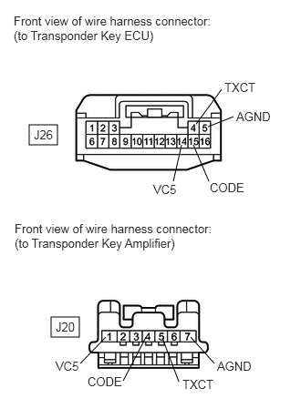
5.CHECK HARNESS AND CONNECTOR (TRANSPONDER KEY ECU - TRANSPONDER KEY AMPLIFIER)
B443042E02
0.333,1.427 0.656,1.656 0.323,0.229 0.583,3.625 0.906,3.854 0.323,0.229 2.24,1.417 2.531,1.021 false 2.375,1.448 2.667,1.333 false 2.208,1.656 2.385,2.073 false 2.073,1.656 1.979,2.073 false 1.208,3.854 0.917,4.156 false 1.667,3.854 1.406,4.354 false 1.854,3.865 2.042,4.365 false 2.177,3.854 2.448,4.156 false 0.156,0.156 2.427,0.531 2.271,0.375 10 false Front view of wire harness connector: (to Transponder Key ECU) 0.167,2.531 2.438,2.885 2.271,0.354 10 false Front view of wire harness connector: (to Transponder Key Amplifier) 0.385,1.458 0.615,1.625 0.229,0.167 10 false J26 0.635,3.656 0.875,3.833 0.24,0.177 10 false J20 2.563,0.917 3.177,1.115 0.615,0.198 10 false TXCT 2.698,1.25 3.313,1.448 0.615,0.198 10 false AGND 2.396,2.063 3.01,2.26 0.615,0.198 10 false CODE 1.75,2.083 2.208,2.281 0.458,0.198 10 false VC5 0.635,4.104 1.094,4.302 0.458,0.198 10 false VC5 1,4.281 1.615,4.479 0.615,0.198 10 false CODE 2.083,4.313 2.698,4.51 0.615,0.198 10 false TXCT 2.479,4.104 3.094,4.302 0.615,0.198 10 false AGND

a.

Disconnect the J26 ECU connector.


b.

Disconnect the J20 amplifier connector.


c.

Measure the resistance according to the value(s) in the table below.

Standard resistance:
Tester Connection Condition Specified Condition
J26-14 (VC5) - J20-1 (VC5) Always Below 1 Ω
J26-15 (CODE) - J20-4 (CODE)
J26-4 (TXCT) - J20-5 (TXCT)
J26-5 (AGND) - J20-7 (AGND)
J26-14 (VC5) or J20-1 (VC5) - Body ground Always 10 kΩ or higher
J26-15 (CODE) or J20-4 (CODE) - Body ground
J26-4 (TXCT) or J20-5 (TXCT) - Body ground
J26-5 (AGND) or J20-7 (AGND) - Body ground


OK

6.REPLACE TRANSPONDER KEY AMPLIFIER

NG

REPAIR OR REPLACE HARNESS OR CONNECTOR

6.REPLACE TRANSPONDER KEY AMPLIFIER
a.

Temporarily replace the transponder key amplifier with a new or normally functioning one (see page Vehicle Interior>ENGINE IMMOBILISER>TRANSPONDER KEY AMPLIFIER>REMOVAL).


NEXT

7.CHECK WHETHER ENGINE STARTS
a.

Check that the engine starts normally.

OK:

Engine starts normally.


OK

END (TRANSPONDER KEY AMPLIFIER IS DEFECTIVE)

NG