METER / GAUGE / DISPLAY METER / GAUGE SYSTEM Speedometer Malfunction
DESCRIPTION
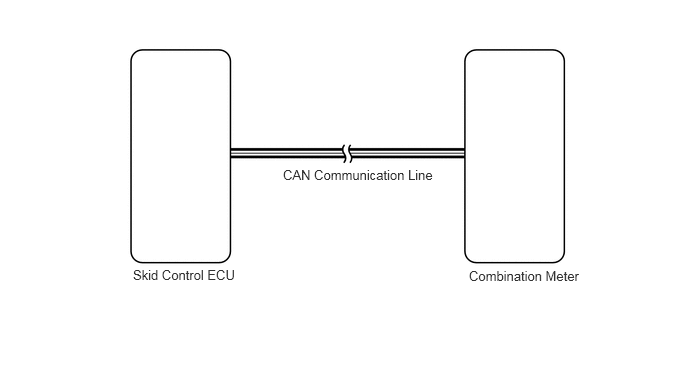
The combination meter receives vehicle speed signals from the skid control ECU via the CAN line. The vehicle speed sensor detects the voltage that varies according to the vehicle speed. The skid control ECU supplies power to the vehicle speed sensor. The skid control ECU detects vehicle speed signals based on the pulses of the voltage.
WIRING DIAGRAM
PROCEDURE
Check if a CAN communication system DTC is output (See page Power Source / Network>CAN COMMUNICATION>CAN COMMUNICATION SYSTEM>DIAGNOSIS SYSTEM).
| Result | Proceed to |
|---|---|
| CAN communication system DTC is not output | A |
| CAN communication system DTC is output | B |
A
B
Check if a SFI system DTC is output.
for 1UR-FE (See page Engine / Hybrid System>1UR-FE ENGINE CONTROL>SFI SYSTEM>DTC CHECK / CLEAR)
for 3UR-FE (See page Engine / Hybrid System>3UR-FE ENGINE CONTROL>SFI SYSTEM>DTC CHECK / CLEAR)
for 3UR-FBE (See page Engine / Hybrid System>3UR-FBE ENGINE CONTROL>SFI SYSTEM>DTC CHECK / CLEAR)
| Result | Proceed to |
|---|---|
| SFI system DTC is not output | A |
| SFI system (for 1UR-FE) DTC is output | B |
| SFI system (for 3UR-FE) DTC is output | C |
| SFI system (for 3UR-FBE) DTC is output | D |
A
B
C
D
Operate the Techstream according to the display and select "Active Test" (See page Vehicle Interior>METER / GAUGE / DISPLAY>METER / GAUGE SYSTEM>DATA LIST / ACTIVE TEST).
| Tester Display | Test Part | Control Range | Diagnostic Note |
|---|---|---|---|
| Speed Meter Operation | Speedometer | 0, 40, 80, 120, 160 or 200 | Acceptable range (km/h or mph): [Control range → Speedometer display]
for mph ·
40 mph → 39 to 42.5 mph ·
80 mph → 79.5 to 84 mph ·
120 mph → 120 to 125.5 mph for km/h ·
40 km/h → 41.7 to 46.2 km/h ·
80 km/h → 83.4 to 88.4 km/h ·
120 km/h → 125.1 to 130.6 km/h ·
160 km/h → 166.2 to 173.2 km/h ·
200 km/h → 207.7 to 215.7 km/h |
- OK:
Needle indication is normal.
- HINT:
- ·
Confirm that the vehicle is stopped and engine is idling. It is normal that door will be locked automatically when performing the speedometer Active Test.
·The displayed value has the same units (km/h, mph) as the main scale of the vehicle's speedometer.
·The needle position should be within the acceptable tolerance.
OK
NG
Operate the Techstream according to the display and select "Data List" (See page Vehicle Interior>METER / GAUGE / DISPLAY>METER / GAUGE SYSTEM>DATA LIST / ACTIVE TEST).
| Tester Display | Measurement Item/Range | Normal Condition | Diagnostic Note |
|---|---|---|---|
| Vehicle Speed Meter | Vehicle speed/Min.: 0 (0), Max.: 255 (158) | Almost same as actual speed (when driving) | Unit: km/h (mph) |
- OK:
Vehicle speed displayed on Techstream is almost the same as actual vehicle speed measured using speedometer tester (calibrated chassis dynamometer).
OK
NG
Operate the Techstream according to the display and select "Data List" (See page Vehicle Interior>METER / GAUGE / DISPLAY>METER / GAUGE SYSTEM>DATA LIST / ACTIVE TEST).
| Tester Display | Measurement Item/Range | Normal Condition | Diagnostic Note |
|---|---|---|---|
| (FL/FR/RL/RR) Wheel Speed | Wheel speed sensor (FL/FR/RL/RR) reading/Min.: 0 (0), Max.: 326 (202) | Actual wheel speed | Similar speed as indicated on speedometer |
- OK:
Vehicle speed displayed on Techstream is almost the same as actual vehicle speed measured using speedometer tester (calibrated chassis dynamometer).
OK
NG