RM27M0U
_56
Audio / Visual / Telematics
_049159
PARK ASSIST / MONITORING
_0234441
INTUITIVE PARKING ASSIST SYSTEM
J
PARK ASSIST / MONITORING INTUITIVE PARKING ASSIST SYSTEM Indicator Circuit
DESCRIPTION
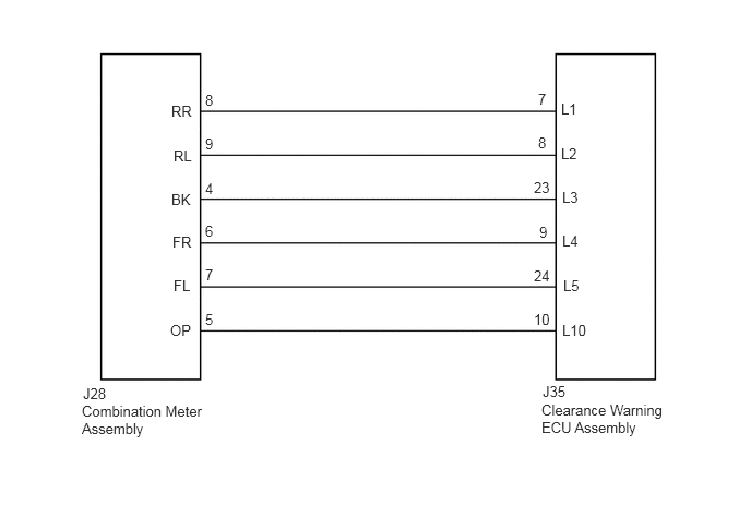
The sonar ON/OFF indicator light and warning indicator lights are installed in the combination meter assembly.
WIRING DIAGRAM
5.177,3.656 5.594,3.823
0.417,0.167
10
false
J35
5.365,3.073 5.781,3.24
0.417,0.167
10
false
L10
5.375,2.646 5.792,2.813
0.417,0.167
10
false
L5
5.365,2.219 5.781,2.385
0.417,0.167
10
false
L4
5.365,1.802 5.781,1.969
0.417,0.167
10
false
L3
5.354,1.385 5.771,1.552
0.417,0.167
10
false
L2
5.354,0.958 5.771,1.125
0.417,0.167
10
false
L1
5.094,2.969 5.292,3.135
0.198,0.167
10
false
10
5.094,2.552 5.292,2.719
0.198,0.167
10
false
24
5.146,2.135 5.344,2.302
0.198,0.167
10
false
9
5.094,1.708 5.292,1.875
0.198,0.167
10
false
23
5.135,1.281 5.333,1.448
0.198,0.167
10
false
8
5.135,0.865 5.333,1.031
0.198,0.167
10
false
7
1.625,3.073 1.896,3.24
0.271,0.167
10
false
OP
1.656,2.646 1.927,2.813
0.271,0.167
10
false
FL
1.646,2.229 1.917,2.396
0.271,0.167
10
false
FR
1.635,1.823 1.906,1.99
0.271,0.167
10
false
BK
1.656,1.406 1.927,1.573
0.271,0.167
10
false
RL
1.635,0.979 1.906,1.146
0.271,0.167
10
false
RR
1.958,2.969 2.156,3.135
0.198,0.167
10
false
5
1.958,2.542 2.156,2.708
0.198,0.167
10
false
7
1.958,2.125 2.156,2.292
0.198,0.167
10
false
6
1.958,1.719 2.156,1.885
0.198,0.167
10
false
4
1.958,1.292 2.156,1.458
0.198,0.167
10
false
9
1.958,0.875 2.156,1.042
0.198,0.167
10
false
8
5.167,3.833 6.479,4.198
1.313,0.365
10
false
Clearance Warning ECU Assembly
0.792,3.677 1.208,3.844
0.417,0.167
10
false
J28
0.781,3.844 2.094,4.208
1.313,0.365
10
false
Combination Meter Assembly
PROCEDURE
1.CHECK HARNESS AND CONNECTOR (CLEARANCE WARNING ECU ASSEMBLY - COMBINATION METER ASSEMBLY)
a.
Disconnect the J35 clearance warning ECU assembly connector.
b.
Disconnect the J28 combination meter assembly connector.
c.
Measure the resistance according to the value(s) in the table below.
- Standard Resistance:
Tester Connection Condition Specified Condition J35-7 (L1) - J28-8 (RR) Always Below 1 Ω J35-8 (L2) - J28-9 (RL) Always Below 1 Ω J35-23 (L3) - J28-4 (BK) Always Below 1 Ω J35-9 (L4) - J28-6 (FR) Always Below 1 Ω J35-24 (L5) - J28-7 (FL) Always Below 1 Ω J35-10 (L10) - J28-5 (OP) Always Below 1 Ω J35-7 (L1) - Body ground Always 10 kΩ or higher J35-8 (L2) - Body ground Always 10 kΩ or higher J35-23 (L3) - Body ground Always 10 kΩ or higher J35-9 (L4) - Body ground Always 10 kΩ or higher J35-24 (L5) - Body ground Always 10 kΩ or higher J35-10 (L10) - Body ground Always 10 kΩ or higher
OK
2.CHECK COMBINATION METER ASSEMBLY
NG
REPAIR OR REPLACE HARNESS OR CONNECTOR
2.CHECK COMBINATION METER ASSEMBLY
a.
Replace the combination meter assembly with a normally functioning or new one (See page Vehicle Interior>METER / GAUGE / DISPLAY>COMBINATION METER>REMOVAL).
b.
Check that the multi-information display in the combination meter assembly operates normally.
- OK:
Multi-information display in the combination meter assembly operates normally.
OK
END (COMBINATION METER ASSEMBLY IS DEFECTIVE)
NG
PROCEED TO NEXT SUSPECTED AREA SHOWN IN PROBLEM SYMPTOMS TABLE