RM27M0U
_57
Power Source / Network
_049168
CAN COMMUNICATION
_0234510
CAN COMMUNICATION SYSTEM
J
CAN COMMUNICATION CAN COMMUNICATION SYSTEM Combination Meter ECU Communication Stop Mode
DESCRIPTION
| Detection Item | Symptom | Trouble Area |
|---|---|---|
| Combination Meter ECU Communication Stop Mode | Either condition is met:
·
"Combination Meter" is not displayed on the "Bus Check" screen. ·
"Combination Meter ECU Communication Stop Mode" in "DTC Combination Table" applies. |
·
Power source or inside combination meter assembly ·
Combination meter assembly |
WIRING DIAGRAM
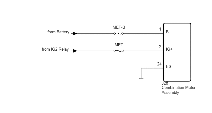
5.465,2.865 6.669,3.250
1.205,0.385
10
Combination Meter Assembly
5.465,2.714 5.798,2.856
0.333,0.142
10
J28
5.609,2.158 6.096,2.296
0.487,0.139
10
ES
5.311,2.07 5.484,2.209
0.173,0.139
10
24
5.376,1.485 5.484,1.623
0.108,0.139
10
2
5.376,0.897 5.484,1.036
0.108,0.139
10
1
5.609,1.572 6.096,1.711
0.487,0.139
10
IG+
5.609,0.985 6.096,1.123
0.487,0.139
10
B
3.875,1.428 4.196,1.567
0.320,0.139
10
MET
3.808,0.837 4.262,0.975
0.453,0.139
10
MET-B
1.414,1.572 2.379,1.711
0.965,0.139
10
from IG2 Relay
1.605,0.987 2.381,1.126
0.776,0.139
10
from Battery
CAUTION / NOTICE / HINT
- NOTICE:
-
Inspect the fuses for circuits related to this system before performing the following inspection procedure.
PROCEDURE
1.CHECK HARNESS AND CONNECTOR (COMBINATION METER ASSEMBLY - BATTERY AND BODY GROUND)
a.
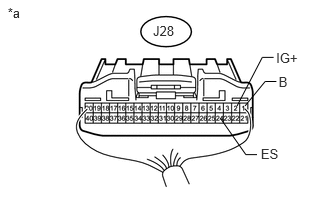
2.469,1.103 2.732,0.597
2.732,0.597 2.85,0.597
false
2.552,1.103 2.761,0.849
2.761,0.849 2.879,0.849
false
2.296,1.232 2.56,1.61
2.56,1.61 2.677,1.61
false
2.717,1.52 2.959,1.662
0.242,0.142
10
ES
2.876,0.517 3.138,0.659
0.262,0.142
10
IG+
2.902,0.775 3.065,0.917
0.163,0.142
10
B
0.08,0.05 0.500,0.192
0.420,0.142
10
*a
1.594,0.241 1.847,0.383
0.253,0.142
10
J28
Disconnect the J28 combination meter assembly connector.
b.
Measure the resistance according to the value(s) in the table below.
- Standard Resistance:
Tester Connection Condition Specified Condition J28-24 (ES) - Body ground Always Below 1 Ω
c.
Measure the voltage according to the value(s) in the table below.
- Standard Voltage:
Tester Connection Condition Specified Condition J28-1 (B) - Body ground Always 11 to 14 V J28-2 (IG+) - Body ground Ignition switch ON 11 to 14 V
| *a | Rear view of wire harness connector
(to Combination Meter Assembly) |
OK
REPLACE COMBINATION METER ASSEMBLY
NG
REPAIR OR REPLACE HARNESS OR CONNECTOR