AXLE AND DIFFERENTIAL FRONT AXLE HUB ON-VEHICLE INSPECTION
CAUTION / NOTICE / HINT
The necessary procedures (adjustment, calibration, initialization, or registration) that must be performed after parts are removed and installed, or replaced during the front axle hub sub-assembly on-vehicle inspection are shown below.
| Replacement Part or Procedure | Necessary Procedures | Effect/Inoperative Function When Necessary Procedures are not Performed | Link |
|---|---|---|---|
| Auxiliary battery terminal is disconnected/reconnected | Memorize steering angle neutral point | Parking assist monitor system | ( ) |
| Panoramic view monitor system | ()
|
- HINT:
- for HV Model
- ·
When the cable is disconnected/reconnected to the auxiliary battery terminal, systems temporarily stop operating. However, each system has a function that completes learning the first time the system is used.
-Learning completes when vehicle is driven
Effect/Inoperative Function When Necessary Procedures are not Performed Necessary Procedures Link Lane tracing assist system Drive the vehicle straight ahead at 35 km/h (22 mph) or more for 5 seconds or more. ( )
Pre-collision system Parking support brake system
-Learning completes when vehicle is operated normally
Effect/Inoperative Function When Necessary Procedures are not Performed Necessary Procedures Link Power door lock control system
·Back door opener
Perform door unlock operation with door control switch or electrical key transmitter sub-assembly switch. ( )
Power back door system Fully close the back door by hand.
- HINT:
-
Initialization is not necessary if the above procedures are performed while the back door is closed.
( )
Air conditioning system After the ignition switch is turned to ON, the servo motor standard position is recognized. -
- HINT:
- ·
Use the same procedure for the RH side and LH side.
·The following procedure is for the LH side.
PROCEDURE

 1. PRECAUTION (for HV Model)
- NOTICE:
-
After turning the ignition switch off, waiting time may be required before disconnecting the cable from the negative (-) auxiliary battery terminal.
-
Click hereGeneral>SETUP>WHEN DISCONNECTING OR RECONNECTING BATTERY TERMINAL>BEFORE DISCONNECTING BATTERY
2. DISABLE BRAKE CONTROL (for HV Model)
- HINT:
-
Click hereBrake>BRAKE (FRONT)>FRONT BRAKE>REMOVAL
3.REMOVE FRONT WHEEL
- HINT:
4.SEPARATE FRONT DISC BRAKE CALIPER ASSEMBLY
- HINT:
-
Click hereDrivetrain>AXLE AND DIFFERENTIAL>FRONT AXLE HUB BOLT>REPLACEMENT
43512
5.REMOVE FRONT DISC
- HINT:
-
Click hereBrake>BRAKE (FRONT)>FRONT BRAKE>REMOVAL
6.INSPECT FRONT AXLE HUB BEARING LOOSENESS
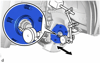
Using a dial indicator with magnetic base, check for looseness near the center of the front axle hub sub-assembly.
- Maximum Looseness:
0.05 mm (0.00197 in.)
- NOTICE:
- ·
Ensure that the dial indicator is set perpendicular to the measurement surface.
·Keep the magnet of the dial indicator away from the front axle hub sub-assembly and front speed sensor.
If the looseness exceeds the maximum, replace the front axle hub sub-assembly.
7.INSPECT FRONT AXLE HUB RUNOUT
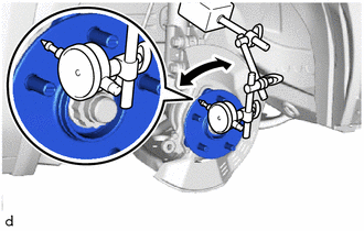
Using a dial indicator with magnetic base, check for runout on the surface of the front axle hub sub-assembly outside the front axle hub bolts.
- Maximum Runout:
0.05 mm (0.00197 in.)
- NOTICE:
- ·
Ensure that the dial indicator is set perpendicular to the measurement surface.
·Make sure to set the tip of the dial indicator towards the outside of the front axle hub bolts.
·Keep the magnet of the dial indicator away from the front axle hub sub-assembly and front speed sensor.
If the runout exceeds the maximum, replace the front axle hub sub-assembly.
43512
8.INSTALL FRONT DISC
- HINT:
9.INSTALL FRONT DISC BRAKE CALIPER ASSEMBLY
- HINT:
-
Click hereDrivetrain>AXLE AND DIFFERENTIAL>FRONT AXLE HUB BOLT>REPLACEMENT
10.INSTALL FRONT WHEEL
- HINT:
11.CONNECT CABLE TO NEGATIVE AUXILIARY BATTERY TERMINAL (for HV Model)
- HINT:
12. INITIALIZATION AFTER RECONNECTING AUXILIARY BATTERY TERMINAL (for HV Model)
- HINT:
-
Click hereGeneral>SETUP>WHEN DISCONNECTING OR RECONNECTING BATTERY TERMINAL>WORK PROCEDURE
-
When disconnecting and reconnecting the auxiliary battery, there is an automatic learning function that completes learning when the respective system is used.
-
Click hereGeneral>SETUP>WHEN DISCONNECTING OR RECONNECTING BATTERY TERMINAL>AUTOMATIC LEARNING CHART