REAR SUSPENSION REAR COIL SPRING(for 2WD) INSTALLATION
CAUTION / NOTICE / HINT
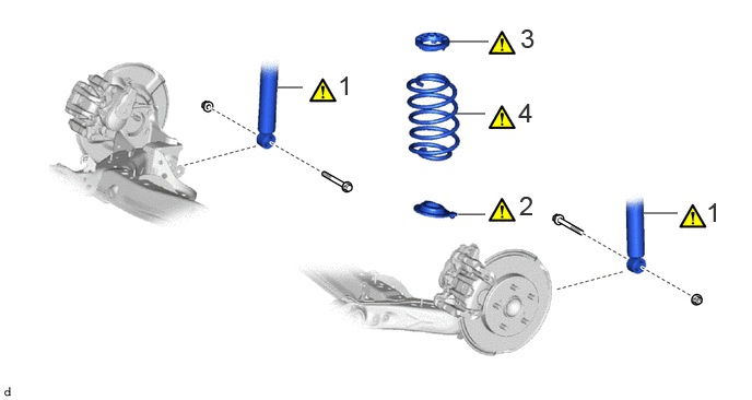
| Procedure | Part Name Code | 
|

|

|
|
|---|---|---|---|---|---|
| 1 | SEPARATE REAR SHOCK ABSORBER ASSEMBLY | - | ( ) |
- | - |
| 2 | REAR LOWER COIL SPRING INSULATOR | 48258C | ()
|
- | - |
| 3 | REAR UPPER COIL SPRING INSULATOR | 48259A | ()
|
- | - |
| 4 | REAR COIL SPRING | 48231B | ()
|
- | - |
| Procedure | Part Name Code |
|
|
|
|
|---|---|---|---|---|---|
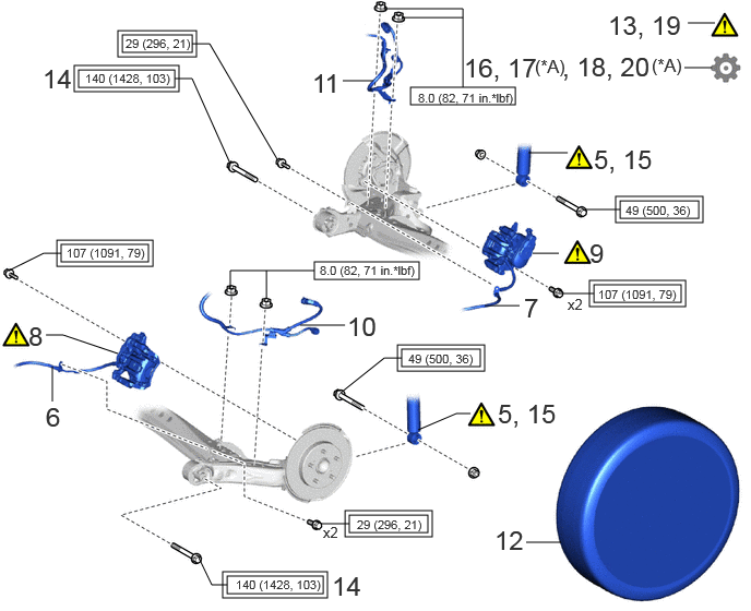
| 5 | CONNECT REAR SHOCK ABSORBER ASSEMBLY | - | ()
|
- | - |
| 6 | REAR FLEXIBLE HOSE LH | 47319F | - | - | - |
| 7 | REAR FLEXIBLE HOSE RH | 47318F | - | - | - |
| 8 | REAR DISC BRAKE CALIPER ASSEMBLY LH | - | ()
|
- | - |
| 9 | REAR DISC BRAKE CALIPER ASSEMBLY RH | - | ()
|
- | - |
| 10 | NO. 2 PARKING BRAKE WIRE ASSEMBLY | 890C0A | - | - | - |
| 11 | NO. 1 PARKING BRAKE WIRE ASSEMBLY | 890C0 | - | - | - |
| 12 | REAR WHEEL | - | - | - | - |
| 13 | STABILIZE SUSPENSION | - | ()
|
- | - |
| 14 | FULLY TIGHTEN REAR AXLE BEAM ASSEMBLY | 42110F | - | - | - |
| 15 | FULLY TIGHTEN REAR SHOCK ABSORBER ASSEMBLY | - | ()
|
- | - |
| 16 | INSPECT REAR WHEEL ALIGNMENT | - | - | - | ()
|
| 17 | CONNECT CABLE TO NEGATIVE AUXILIARY BATTERY TERMINAL | - | - | - | ()
|
| 18 | PERFORM INITIALIZATION | - | - | - | ()
|
| 19 | CHECK FOR SPEED SENSOR SIGNAL | - | ()
|
- | - |
| 20 | INITIALIZATION AFTER RECONNECTING AUXILIARY BATTERY TERMINAL | - | - | - | ()
|
| *A | for HV Model | - | - |

|
Tightening torque for "Major areas involving basic vehicle performance such as moving/turning/stopping" : N*m (kgf*cm, ft.*lbf) | 
|
N*m (kgf*cm, ft.*lbf): Specified torque |
CAUTION / NOTICE / HINT
- HINT:
- ·
Use the same procedure for the RH side and LH side.
·The following procedure is for the LH side.
PROCEDURE

 1.SEPARATE REAR SHOCK ABSORBER ASSEMBLY
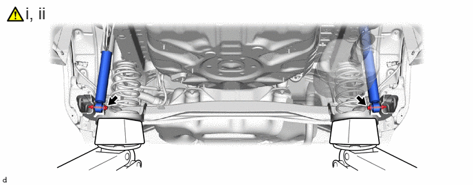
Remove the 2 bolts and 2 nuts, and separate the rear axle beam assembly from the rear shock absorber assemblies LH and RH.
- NOTICE:
-
Because the nuts have their own stoppers, do not turn the nuts. Loosen the bolts with the nuts secured.
Slowly lower the rear axle beam assembly using 2 jacks and 2 wooden blocks.
48258C
2.INSTALL REAR LOWER COIL SPRING INSULATOR
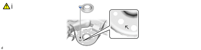
Install the rear lower coil spring insulator to the rear axle beam assembly.
- NOTICE:
-
Securely insert the protrusion of the rear lower coil spring insulator into the guide holes of the rear axle beam assembly.
48259A
3.INSTALL REAR UPPER COIL SPRING INSULATOR
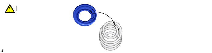
Install the rear upper coil spring insulator to the rear coil spring.
- NOTICE:
- ·
Install the rear upper coil spring insulator so that the dimension between the stopper and upper end of the rear coil spring is 10 mm (0.394 in.) or less.
·The identification mark of the rear coil spring should be towards the underside.
48231B
4.INSTALL REAR COIL SPRING
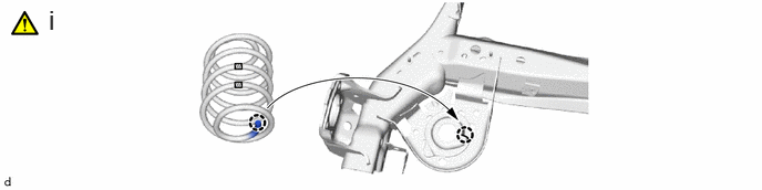

|
Identification Mark | - | - |
Set the rear coil spring to the rear axle beam assembly.
- NOTICE:
- ·
Make sure that there is no gap between the coil end of the rear coil spring and the stopper of the rear lower coil spring insulator.
·Set the rear coil spring so that the identification mark is positioned as shown in the illustration.
5.CONNECT REAR SHOCK ABSORBER ASSEMBLY
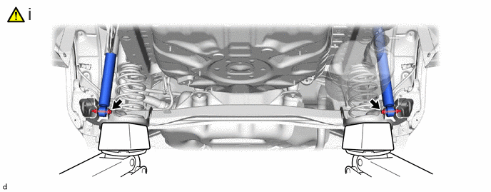
Slowly jack up the rear axle beam assembly using 2 jacks and 2 wooden blocks and temporarily install the rear shock absorber assemblies LH and RH with the 2 bolts and 2 nuts.
- NOTICE:
-
Because the nuts have their own stoppers, do not turn the nuts. Tighten the bolts with the nuts secured.
47319F
6.INSTALL REAR FLEXIBLE HOSE LH
- Torque:
- 29 N*m (296 kgf*cm, 21 ft.*lbf)
47318F
7.INSTALL REAR FLEXIBLE HOSE RH
8.INSTALL REAR DISC BRAKE CALIPER ASSEMBLY LH
|
|
Click here()
|
9.INSTALL REAR DISC BRAKE CALIPER ASSEMBLY RH
10.INSTALL NO. 2 PARKING BRAKE WIRE ASSEMBLY
- Torque:
- 8.0 N*m (82 kgf*cm, 71 in.*lbf)
11.INSTALL NO. 1 PARKING BRAKE WIRE ASSEMBLY
12.INSTALL REAR WHEEL
13. STABILIZE SUSPENSION
42110F
14.FULLY TIGHTEN REAR AXLE BEAM ASSEMBLY
- Torque:
- 140 N*m (1428 kgf*cm, 103 ft.*lbf)
48540
15.FULLY TIGHTEN REAR SHOCK ABSORBER ASSEMBLY
|
|
|
- Torque:
- 49 N*m (500 kgf*cm, 36 ft.*lbf)
16.INSPECT REAR WHEEL ALIGNMENT
17.CONNECT CABLE TO NEGATIVE AUXILIARY BATTERY TERMINAL (for HV Model)
18.CHECK FOR SPEED SENSOR SIGNAL
19.PERFORM INITIALIZATION
| Parking support brake system | ()
|
| Parking assist monitor system | ()
|
| Panoramic view monitor system | ()
|
20. INITIALIZATION AFTER RECONNECTING AUXILIARY BATTERY TERMINAL (for HV Model)
Click hereGeneral>SETUP>WHEN DISCONNECTING OR RECONNECTING BATTERY TERMINAL>WORK PROCEDURE
- HINT:
-
When disconnecting and reconnecting the auxiliary battery, there is an automatic learning function that completes learning when the respective system is used.
-
Click hereGeneral>SETUP>WHEN DISCONNECTING OR RECONNECTING BATTERY TERMINAL>AUTOMATIC LEARNING CHART