HYBRID / BATTERY CONTROL REAR INVERTER INSTALLATION
CAUTION / NOTICE / HINT
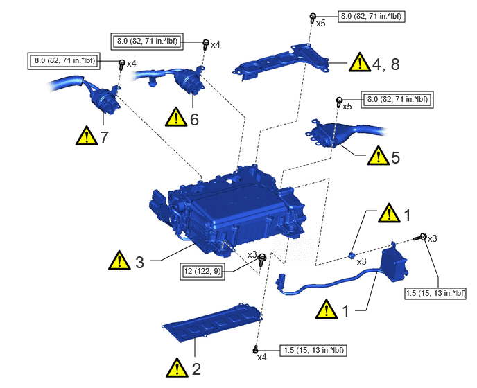
| Procedure | Part Name Code | 
|

|

|
|
|---|---|---|---|---|---|
| 1 | HV INVERTER COOLING FAN | G92B1 | ( ) |
- | - |
| 2 | HV INVERTER COOLING COVER | G92B2 | ()
|
- | - |
| 3 | REAR HYBRID MOTOR CONTROL INVERTER ASSEMBLY | G92B0 | ()
|
- | - |
| 4 | REMOVE INVERTER TERMINAL COVER | G9223 | ()
|
- | - |
| 5 | REAR TRACTION MOTOR CABLE | - | ()
|
- | - |
| 6 | HV BATTERY PACK WIRECAUTION: | 821H3 | ()
|
- | - |
| 7 | HV FLOOR UNDER WIRE | 821H1 | ()
|
- | - |
| 8 | INSTALL INVERTER TERMINAL COVER | G9223 | ()
|
- | - |

|
Tightening torque for "Major areas involving basic vehicle performance such as moving/turning/stopping" : N*m (kgf*cm, ft.*lbf) | 
|
N*m (kgf*cm, ft.*lbf): Specified torque |
| Procedure | Part Name Code |
|
|
|
|
|---|---|---|---|---|---|
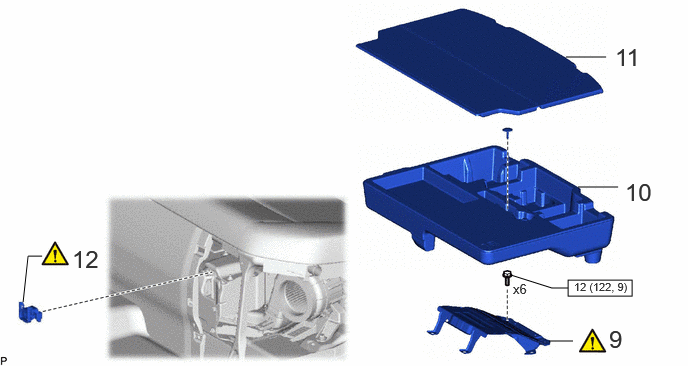
| 9 | HYBRID INVERTER PROTECTOR ASSEMBLY | G92D0 | ()
|
- | - |
| 10 | REAR DECK FLOOR BOX | 64993 | - | - | - |
| 11 | DECK BOARD ASSEMBLY | 58410B | - | - | - |
| 12 | SERVICE PLUG GRIP | G3834 | ()
|
- | - |
|
|
N*m (kgf*cm, ft.*lbf): Specified torque | - | - |
PROCEDURE

 G92B1
1.INSTALL HV INVERTER COOLING FAN
|
|
|
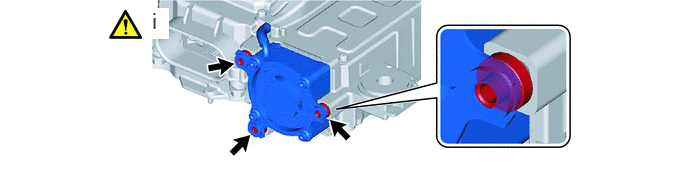
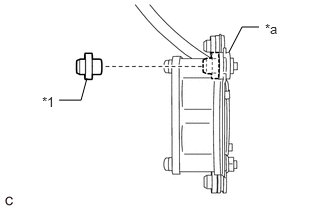
Install the 3 collars to the bushes of the HV inverter cooling fan.
- HINT:
- ·
 0.615,1.042 0.844,1.042 0.844,1.042 0.906,0.813 false 2.385,0.542 2.521,0.281 2.521,0.281 2.698,0.281 false 0.438,0.979 0.698,1.208 0.26,0.229 10 false *1 2.76,0.219 3.021,0.448 0.26,0.229 10 false *a
*1 collar *a bush
Be sure to install the collar in the correct orientation.
·If any of the bushes have come off, reinstall the bushes to the HV inverter cooling fan before installing the collars.
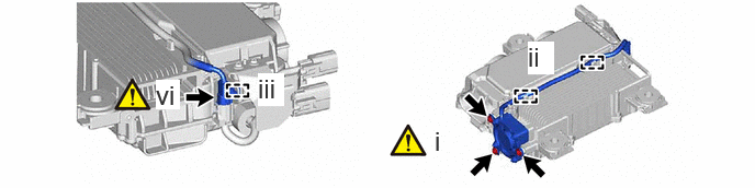
Using a T20 "TORX" socket wrench, install the HV inverter cooling fan with 3 bolts..
- Torque:
- 1.5 N*m (15 kgf*cm, 13 in.*lbf)
- HINT:
-
When replacing the installation bolts:
- ·
The shape of supply part bolts will differ.
·The supply part bolts do not come with washers, so be sure to prepare washers when replacing them.
·When tightening the supply bolts, use a plus socket wrench.
Engage the 2 guides.
Engage the clamp.
Connect the hybrid motor control inverter assembly connector.
G92B2
2.INSTALL HV INVERTER COOLING COVER
|
|
|
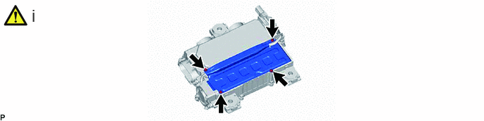
Using a T20 "TORX" socket wrench, install the HV inverter cooling cover with 4 bolts.
- Torque:
- 1.5 N*m (15 kgf*cm, 13 in.*lbf)
- HINT:
-
When replacing the installation bolts:
- ·
The shape of supply part bolts will differ.
·The supply part bolts do not come with washers, so be sure to prepare washers when replacing them.
·When tightening the supply bolts, use a plus socket wrench.
G92B0
3.INSTALL REAR HYBRID MOTOR CONTROL INVERTER ASSEMBLY
|
|
|
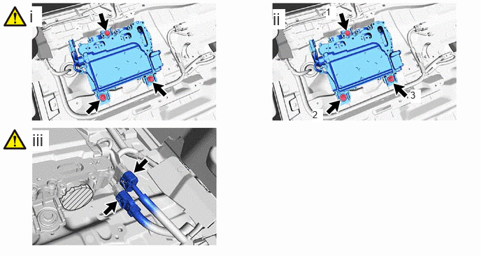
Temporarily install the rear hybrid motor control inverter assembly with 3 bolts.
- NOTICE:
- ·
Do not damage the terminals, connector housing or rear hybrid motor control inverter assembly during disconnection.
·Cover the hole where the cable was connected with tape (non-residue type) or equivalent to prevent entry of foreign matter.
·Do not allow any foreign matter or water to enter the rear hybrid motor control inverter assembly.
·Insulate the disconnected terminals with insulating tape.
·To prevent damage due to staticelectricity, do not touch the terminals of the disconnected connectors.
Fully tighten the 3 bolts as shown in the illustration.
- Torque:
- 12 N*m (122 kgf*cm, 9 ft.*lbf)
Connect the 2 rear hybrid motor control inverter assembly connectors.
- NOTICE:
-
To prevent damage due to staticelectricity, do not touch the terminalsof the disconnected connectors.
G9223
4.REMOVE INVERTER TERMINAL COVER
|
|
Click here()
|
5.CONNECT REAR TRACTION MOTOR CABLE
|
|
|
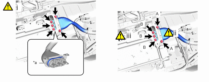
| *a | Waterproof Seal | - | - |
Temporarily install the rear traction motor cable with the 5 bolts.
- NOTICE:
- ·
Cover the hole where the cable was connected with tape (non-residue type) or equivalent to prevent entry of foreign matter.
·Do not allow any foreign matter or water to enter the rear hybrid motor control inverter assembly.
·Insulate the disconnected terminals with insulating tape.
·To prevent damage due to staticelectricity, do not touch the terminals of the disconnected connectors.
Using an insulated tool, fully tighten 2 bolts (A).
- Torque:
- 8.0 N*m (82 kgf*cm, 71 in.*lbf)
Using an insulated tool, fully tighten 3 bolts (B).
821H3
6.CONNECT HV BATTERY PACK WIRE
|
|
|
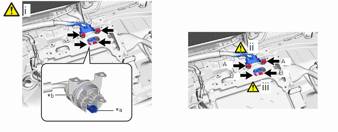
| *a | Interlock | *b | Waterproof Seal |
Temporarily install the HV battery pack wire with the 4 bolts..
- NOTICE:
- ·
Cover the hole where the cable was connected with tape (non-residue type) or equivalent to prevent entry of foreign matter.
·Do not allow any foreign matter or water to enter the rear hybrid motor control inverter assembly.
·Insulate the disconnected terminals with insulating tape.
·To prevent damage due to staticelectricity, do not touch the terminals of the disconnected connectors.
Using an insulated tool, install 2 bolts (A).
- Torque:
- 8.0 N*m (82 kgf*cm, 71 in.*lbf)
Using an insulated tool, install 2 bolts (B).
- Torque:
- 8.0 N*m (82 kgf*cm, 71 in.*lbf)
821H1
7.CONNECT FLOOR UNDER WIRE
|
|
|
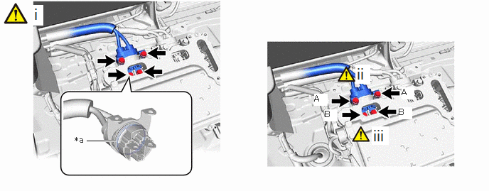
| *a | Waterproof Seal | - | - |
Temporarily install the HV floor under wire with the 4 bolts.
- NOTICE:
- ·
Cover the hole where the cable was connected with tape (non-residue type) or equivalent to prevent entry of foreign matter.
·Do not allow any foreign matter or water to enter the inverter with converter assembly.
·Insulate the disconnected terminals with insulating tape.
·To prevent damage due to staticelectricity, do not touch the terminalsof the disconnected connectors.
Using an insulated tool, fully tighten 2 bolts (A).
- Torque:
- 8.0 N*m (82 kgf*cm, 71 in.*lbf)
Using an insulated tool, fully tighten 2 bolts (B).
- Torque:
- 8.0 N*m (82 kgf*cm, 71 in.*lbf)
G9223
8.INSTALL INVERTER TERMINAL COVER
|
|
|
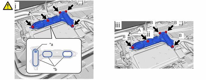
| *a | Interlock | *b | Waterproof Seal |
Temporarily install the inverter terminal cover with the 5 bolts.
- NOTICE:
- ·
Cover the hole where the cable was connected with tape (non-residue type) or equivalent to prevent entry of foreign matter.
·Do not allow any foreign matter or water to enter the rear hybrid motor control inverter assembly.
·Insulate the disconnected terminals with insulating tape.
·To prevent damage due to staticelectricity, do not touch the terminals of the disconnected connectors.
Fully tighten bolt (A).
- Torque:
- 8.0 N*m (82 kgf*cm, 71 in.*lbf)
Fully tighten 4 bolts (B).
- Torque:
- 8.0 N*m (82 kgf*cm, 71 in.*lbf)
G92D0
9.INSTALL HYBRID INVERTER PROTECTOR ASSEMBLY
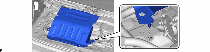
Insert the positioning pin on the hybrid inverter protector assembly into the positioning hole on the vehicle body side to align the parts.
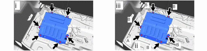
Temporarily install the hybrid inverter protector assembly with the 6 bolts.
Fully tighten bolt (A).
- Torque:
- 12 N*m (122 kgf*cm, 9 ft.*lbf)
Fully tighten 5 bolts (B).
- Torque:
- 12 N*m (122 kgf*cm, 9 ft.*lbf)
64993
10.INSTALL REAR DECK FLOOR BOX
58410B
11.INSTALL DECK BOARD ASSEMBLY
G3834
12.INSTALL SERVICE PLUG GRIP