PARKING BRAKE ELECTRIC PARKING BRAKE ACTUATOR(for AWD) REMOVAL
CAUTION / NOTICE / HINT
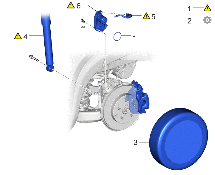
| Procedure | Part Name Code | 
|

|

|
|
|---|---|---|---|---|---|
| 1 | PRECAUTION | - | ( ) |
- | - |
| 2 | RELEASE PARKING BRAKE | - | ()
|
- | - |
| 3 | REAR WHEEL | - | - | - | - |
| 4 | SHOCK ABSORBER ASSEMBLY REAR LH | 48540 | ()
|
- | - |
| 5 | NO. 2 PARKING BRAKE WIRE ASSEMBLY | 890C0A | ()
|
- | - |
| 6 | PARKING BRAKE ACTUATOR ASSEMBLY | 46310B | ()
|
- | - |
| ● | Non-reusable part | - | - |
CAUTION / NOTICE / HINT
The necessary procedures (adjustment, calibration, initialization, or registration) that must be performed after parts are removed and installed, or replaced during the rear coil spring removal/installation are shown below.
| Replacement Part or Procedure | Necessary Procedures | Effect/Inoperative Function When Necessary Procedures are not Performed | Link |
|---|---|---|---|
| for HV Model:
Auxiliary battery terminal is disconnected/reconnected |
Memorize steering angle neutral point | Parking assist monitor system | ()
|
| Panoramic view monitor system | ()
|
||
| Rear wheel alignment adjustment | 1.
Perform "Reset Memory" 2.
Perform calibration (linear solenoid valve offset learning, SM solenoid valve offset learning, brake pedal stroke sensor assembly zero point calibration, system information memorization, and yaw rate and acceleration sensor zero point calibration) |
·
DTCs are stored ·
ABS warning light illuminates ·
Brake system warning light (yellow indicator) ·
Slip indicator light illuminates ·
VSC disabled or malfunctions |
()
|
| Suspension, tires, etc.
(The vehicle height changes because of suspension or tire replacement.) |
·
Ultrasonic sensor detection angle ·
Ultrasonic sensor detection angle registration |
Parking support brake system | ()
|
| Rear television camera assembly optical axis (Back camera position setting) | Parking assist monitor system | ()
|
|
·
Parking assist ECU initialization ·
Adjust steering angle |
Panoramic view monitor system | ()
|
- HINT:
- ·
Use the same procedure for the RH side and LH side.
·The following procedure is for the LH side.
PROCEDURE

 1. PRECAUTION
2.RELEASE PARKING BRAKE
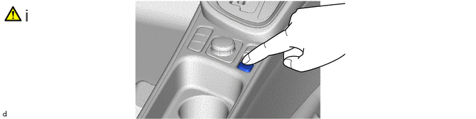
Perform the following procedure.
1. Move the shift lever to P.
2. Turn the ignition switch ON.
3. Operate the electric parking brake switch assembly to release the parking brake.
- HINT:
-
If the parking brake cannot be released:
-
Click hereBrake>PARKING BRAKE>FORCED RELEASE>OPERATION METHOD
4. Turn the ignition switch off.
3.REMOVE REAR WHEEL
48540
4.DISCONNECT SHOCK ABSORBER ASSEMBLY REAR LH
|
|
Click here()
|
890C0A
5.DISCONNECT NO. 2 PARKING BRAKE WIRE ASSEMBLY
|
|
|

46310B
6.REMOVE PARKING BRAKE ACTUATOR ASSEMBLY
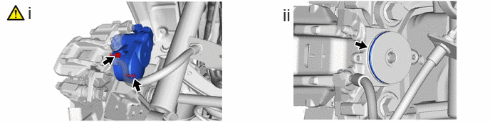
Using a 5 mm hexagon socket wrench, remove the 2 bolts and parking brake actuator assembly from the rear disc brake cylinder assembly.
- NOTICE:
- ·
Check for brake fluid leaks on the back side of the rear disc brake cylinder assembly.
·If there are any brake fluid leaks, replace the rear disc brake cylinder assembly.
Remove the O-ring from the rear disc brake cylinder assembly.