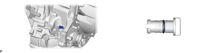
EC6D MANUAL TRANSMISSION / TRANSAXLE MANUAL TRANSAXLE ASSEMBLY(When Not Using the Engine Support Bridge) REMOVAL
CAUTION / NOTICE / HINT
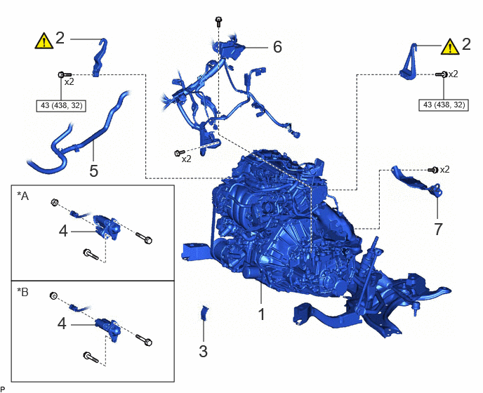
| Procedure | Part Name Code | 
|

|

|
|
|---|---|---|---|---|---|
| 1 | ENGINE ASSEMBLY WITH TRANSAXLE | - | - | - | - |
| 2 | ENGINE HANGERS | - | ( ) |
- | - |
| 3 | FLYWHEEL HOUSING SIDE COVER | 11363A | - | - | - |
| 4 | STARTER ASSEMBLY | 28100 | - | - | - |
| 5 | NO. 3 WATER BY-PASS HOSE ASSEMBLY | 16290F | - | - | - |
| 6 | ENGINE WIRE | 82121 | - | - | - |
| 7 | DRIVE SHAFT HEAT INSULATOR SUB-ASSEMBLY | 43409E | - | - | - |
| *A | w/ Stop and Start System | *B | w/o Stop and Start System |

|
N*m (kgf*cm, ft.*lbf): Specified torque | - | - |
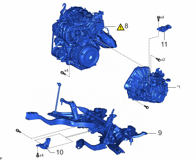
| Procedure | Part Name Code |
|
|
|
|
|---|---|---|---|---|---|
| 8 | ENGINE ASSEMBLY | - | ()
|
- | - |
| 9 | FRONT SUSPENSION CROSSMEMBER SUB-ASSEMBLY | 51201 | - | - | - |
| 10 | NO. 2 ENGINE MOVING CONTROL ROD | 12364B | - | - | - |
| 11 | ENGINE MOUNTING BRACKET LH | 12325A | - | - | - |
| *1 | MANUAL TRANSAXLE ASSEMBLY | - | - |
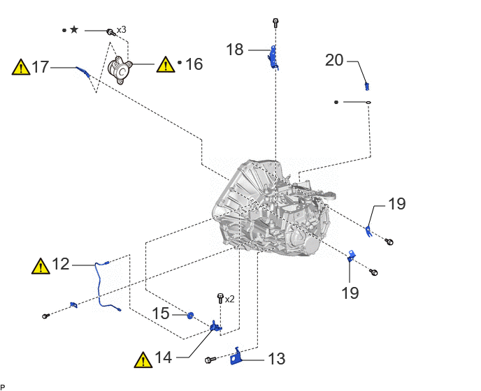
| Procedure | Part Name Code |
|
|
|
|
|---|---|---|---|---|---|
| 12 | CLUTCH RELEASE CYLINDER TO FLEXIBLE HOSE TUBE | 31482 | ()
|
- | - |
| 13 | CLUTCH FLEXIBLE HOSE BRACKET | 31484 | - | - | - |
| 14 | CLUTCH RELEASE BLEEDER SUB-ASSEMBLY | 31407B | ()
|
- | - |
| 15 | CLUTCH TUBE BOOT | 31126B | - | - | - |
| 16 | CLUTCH RELEASE CYLINDER WITH BEARING ASSEMBLY | 31400 | ()
|
- | - |
| 17 | BLEEDER CLUTCH RELEASE TUBE | 31483 | ()
|
- | - |
| 18 | HEATER BRACKET | 87121V | - | - | - |
| 19 | WIRE HARNESS CLAMP BRACKET | - | - | - | - |
| 20 | TRANSMISSION CASE PLUG ASSEMBLY | 35150D | - | - | - |
| ● | Non-reusable part | ★ | Precoated part |
CAUTION / NOTICE / HINT
- CAUTION:
- ·
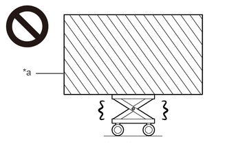 0.542,1.115 0.958,1.115 false 0.344,1.01 0.656,1.208 0.313,0.198 10 false *a
*a Heavy object exceeding the capacity of the engine lifter
Because the weight of the engine with transaxle assembly is extremely heavy, make sure to follow the work procedures described in the repair manual.
·If work is not performed according to the procedures described in the repair manual, there is a danger that the engine lifter could drop and components could fall down.
·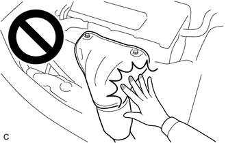
Do not touch the engine, exhaust manifold or other high temperature components when they are hot.
·Touching the engine, exhaust manifold or other high temperature components when they are hot could result in burns.
- NOTICE:
-
When the manual transaxle assembly is removed, be sure to use a new clutch release cylinder with bearing assembly and new installation bolts. Removal of the manual transaxle assembly allows the compressed clutch release cylinder with bearing assembly to return to its original position. Dust from the moving section may damage the seal of the clutch release cylinder with bearing assembly, possibly causing clutch fluid leaks.
- HINT:
-
When the cable is disconnected / reconnected to the auxiliary battery terminal, systems temporarily stop operating. However, each system has a function that completes learning the first time the system is used.
- ·
Learning completes when vehicle is driven
Effect/Inoperative Function When Necessary Procedures are not Performed Necessary Procedures Link Lane tracing assist system Drive the vehicle straight ahead at 35 km/h (22 mph) or more for 5 second or more. ( )
Pre-collision system Stop and start system Drive the vehicle until stop and start control is permitted (approximately 5 to 60 minutes) ( )
·Learning completes when vehicle is operated normally
Effect/Inoperative Function When Necessary Procedures are not Performed Necessary Procedures Link Power door lock control system
·Back door opener
Perform door unlock operation with door control switch or electrical key transmitter sub-assembly switch. ( )
Power back door system Fully close the back door by hand.
- HINT:
-
Initialization is not necessary if the above procedures are performed while the back door is closed.
( )
Air conditioning system After the ignition switch is turned to ON, the servo motor standard position is recognized. -
PROCEDURE

 1.REMOVE ENGINE ASSEMBLY WITH TRANSAXLE
2.INSTALL ENGINE HANGERS
|
|
Click here()
|
11363A
3.REMOVE FLYWHEEL HOUSING SIDE COVER
w/ Stop and Start System:
Click hereEngine / Hybrid System>M15A-FKS (STARTING)>STARTER (w/ Stop And Start System)>REMOVAL
w/o Stop and Start System:
Click hereEngine / Hybrid System>M15A-FKS (STARTING)>STARTER (w/o Stop And Start System)>REMOVAL
28100
4.REMOVE STARTER ASSEMBLY
w/ Stop and Start System:
Click hereEngine / Hybrid System>M15A-FKS (STARTING)>STARTER (w/ Stop And Start System)>REMOVAL
w/o Stop and Start System:
Click hereEngine / Hybrid System>M15A-FKS (STARTING)>STARTER (w/o Stop And Start System)>REMOVAL
16290F
5.SEPARATE NO. 3 WATER BY-PASS HOSE ASSEMBLY
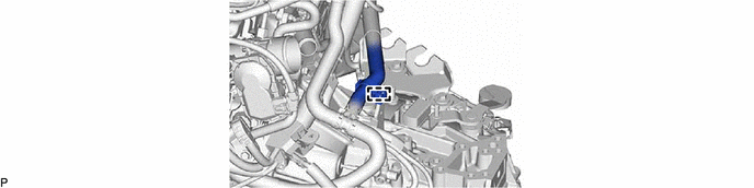
82121
6.DISCONNECT ENGINE WIRE
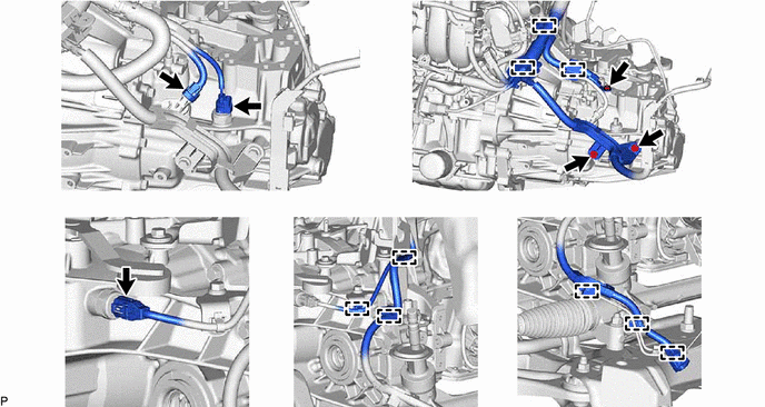
43409E
7.REMOVE DRIVE SHAFT HEAT INSULATOR SUB-ASSEMBLY
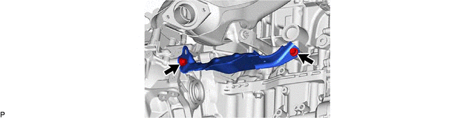
8.REMOVE ENGINE ASSEMBLY
|
|
|
51201
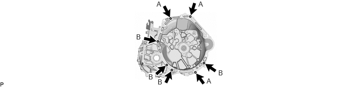
9.REMOVE FRONT SUSPENSION CROSSMEMBER SUB-ASSEMBLY
12364B
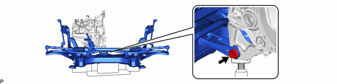
10.REMOVE NO. 2 ENGINE MOVING CONTROL ROD
12325A
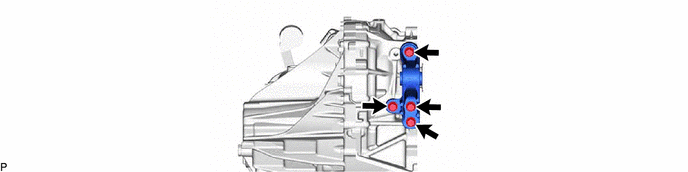
11.REMOVE ENGINE MOUNTING BRACKET LH
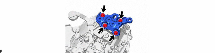
31482
12.REMOVE CLUTCH RELEASE CYLINDER TO FLEXIBLE HOSE TUBE
|
|
Click here()
|
31484
13.REMOVE CLUTCH FLEXIBLE HOSE BRACKET
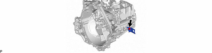
31407B
14.REMOVE CLUTCH RELEASE BLEEDER SUB-ASSEMBLY
|
|
Click here()
|
31126B
15.REMOVE CLUTCH TUBE BOOT
Click hereDrivetrain>CLUTCH>CLUTCH UNIT>REMOVAL
31400
16.REMOVE CLUTCH RELEASE CYLINDER WITH BEARING ASSEMBLY
|
|
Click here()
|
31483
17.REMOVE BLEEDER CLUTCH RELEASE TUBE
|
|
Click here()
|
87121V
18.REMOVE HEATER BRACKET
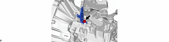
19.REMOVE WIRE HARNESS CLAMP BRACKET
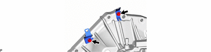
35150D
20.REMOVE TRANSMISSION CASE PLUG ASSEMBLY