BRAKE SYSTEM (OTHER) BRAKE PEDAL(for HV Model LHD) REMOVAL
CAUTION / NOTICE / HINT
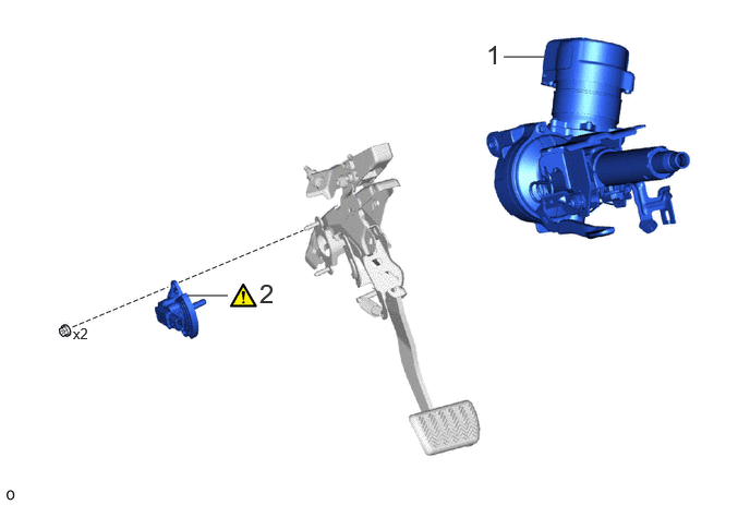
| Procedure | Part Name Code | 
|

|

|
|
|---|---|---|---|---|---|
| 1 | STEERING COLUMN ASSEMBLY | - | - | - | - |
| 2 | BRAKE PEDAL STROKE SENSOR ASSEMBLY | 89510D | ( ) |
- | - |
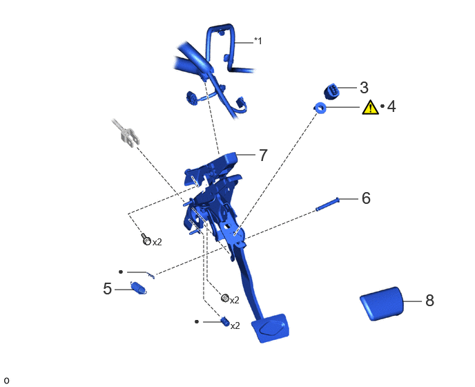
| Procedure | Part Name Code |
|
|
|
|
|---|---|---|---|---|---|
| 3 | STOP LIGHT SWITCH ASSEMBLY | 84340 | - | - | - |
| 4 | STOP LIGHT SWITCH MOUNTING ADJUSTER | 84345 | ()
|
- | - |
| 5 | BRAKE PEDAL RETURN SPRING | 47101A | - | - | - |
| 6 | PUSH ROD PIN | 47264A | - | - | - |
| 7 | BRAKE PEDAL SUPPORT ASSEMBLY | 47110 | - | - | - |
| 8 | BRAKE PEDAL PAD | 47121 | - | - | - |
| *1 | ENGINE ROOM MAIN WIRE | - | - |
| ● | Non-reusable part | - | - |
CAUTION / NOTICE / HINT
The necessary procedures (adjustment, calibration, initialization, or registration) that must be performed after parts are removed, installed, or replaced during brake pedal support assembly removal/installation are shown below.
| Replaced Part or Performed Procedure | Necessary Procedure | Effect/Inoperative Function when Necessary Procedure not Performed | Link |
|---|---|---|---|
| Auxiliary battery terminal is disconnected/reconnected | Memorize steering angle neutral point | Parking assist monitor system | ()
|
| Panoramic view monitor system (w/o Advanced Park) | ()
|
||
| Replacement of brake pedal support assembly | 1.
Perform "Reset Memory" 2.
Perform calibration |
·
DTCs are stored ·
ABS warning light illuminates ·
Brake system warning light (yellow indicator) illuminates ·
Slip indicator light illuminates ·
VSC disabled or malfunctions |
()
|
- NOTICE:
- ·
When disassembling the brake pedal support assembly, do not loosen the breakaway bolt at the time of collisions.
·If the breakaway bolt at the time of collisions is loosened, replace with a new brake pedal support assembly.
·While the auxiliary battery is connected, even if the ignition switch is off, the brake control system activates when the brake pedal is depressed or any door courtesy switch turns on. Therefore, when servicing the brake system components, do not operate the brake pedal or open/close the doors while the auxiliary battery is connected.
- HINT:
-
When the cable is disconnected / reconnected to the auxiliary battery terminal, systems temporarily stop operating. However, each system has a function that completes learning the first time the system is used.
- ·
Learning completes when vehicle is driven
Effect/Inoperative Function When Necessary Procedures are not Performed Necessary Procedures Link Lane tracing assist system Drive the vehicle straight ahead at 35 km/h (22 mph) or more for 5 second or more. ( )
Pre-collision system Parking support brake system
·Learning completes when vehicle is operated normally
Effect/Inoperative Function When Necessary Procedures are not Performed Necessary Procedures Link Power door lock control system
·Back door opener
Perform door unlock operation with door control switch or electrical key transmitter sub-assembly switch. ( )
Power back door system Fully close the back door by hand.
- HINT:
-
Initialization is not necessary if the above procedures are performed while the back door is closed.
( )
Air conditioning system After the ignition switch is turned to ON, the servo motor standard position is recognized. -
PROCEDURE

 1.REMOVE STEERING COLUMN ASSEMBLY
89510D
2.REMOVE BRAKE PEDAL STROKE SENSOR ASSEMBLY
|
|
Click here()
|
84340
3.REMOVE STOP LIGHT SWITCH ASSEMBLY
84345
4.REMOVE STOP LIGHT SWITCH MOUNTING ADJUSTER
|
|
Click here()
|
47101A
5.REMOVE BRAKE PEDAL RETURN SPRING

47264A
6.REMOVE PUSH ROD PIN

47110
7.REMOVE BRAKE PEDAL SUPPORT ASSEMBLY
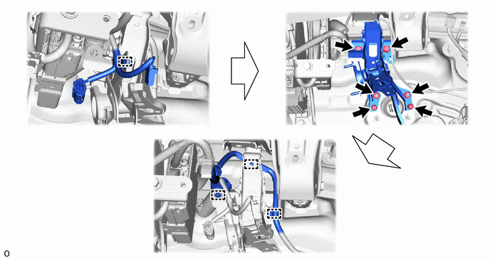
47121
8.REMOVE BRAKE PEDAL PAD