M15A-FXE ENGINE CONTROL AIR FUEL RATIO SENSOR(for Sensor 2) INSTALLATION
CAUTION / NOTICE / HINT
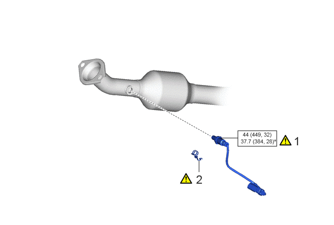
| Procedure | Part Name Code | 
|

|

|
|
|---|---|---|---|---|---|
| 1 | NO. 2 AIR FUEL RATIO SENSOR | 89467C | ( ) |
- | - |
| 2 | WIRE HARNESS CLAMP BRACKET | - | ()
|
- | - |

|
N*m (kgf*cm, ft.*lbf): Specified torque | * | For use with SST |
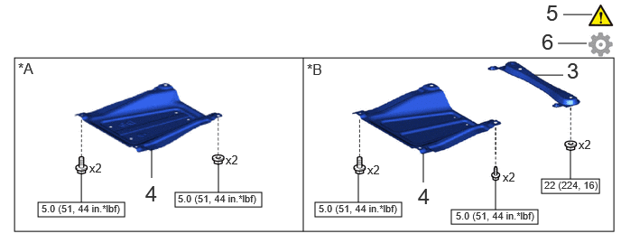
| Procedure | Part Name Code |
|
|
|
|
|---|---|---|---|---|---|
| 3 | CENTER NO. 1 FLOOR BRACE | 57543C | - | - | - |
| 4 | CENTER NO. 4 ENGINE UNDER COVER | 51447D | - | - | - |
| 5 | INSPECT FOR EXHAUST GAS LEAK | - | ()
|
- | - |
| 6 | PERFORM INITIALIZATION | - | - | - | ()
|
| *A | for TMC Made | *B | for TMMF Made |
|
|
N*m (kgf*cm, ft.*lbf): Specified torque | - | - |
PROCEDURE

 89467C
1.INSTALL NO. 2 AIR FUEL RATIO SENSOR
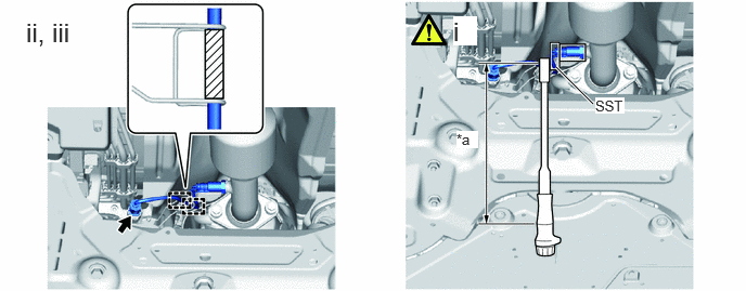
| *a | Torque Wrench Fulcrum Length | - | - |
Using SST, install the No. 2 air fuel ratio sensor to the front exhaust pipe assembly.
- SST
- 09224-00012
- Torque:
- Specified tightening torque : 44 N*m (449 kgf*cm, 32 ft.*lbf)
- NOTICE:
-
If the No. 2 air fuel ratio sensor has been struck or dropped, replace it.
- HINT:
- ·
Calculate the torque wrench reading when changing the fulcrum length of the torque wrench.
Click hereGeneral>INTRODUCTION>REPAIR INSTRUCTION>PRECAUTION
·When using SST (fulcrum length of 30 mm (1.18 in.)) + torque wrench (fulcrum length of 180 mm (7.09 in.)):
37.7 N*m (384 kgf*cm, 28 ft.*lbf)
Engage the 2 wire harness clamp.
- NOTICE:
-
Make sure the white tube is between the wires.
Connect the No. 2 air fuel ratio sensor connector.
2.INSTALL WIRE HARNESS CLAMP BRACKET
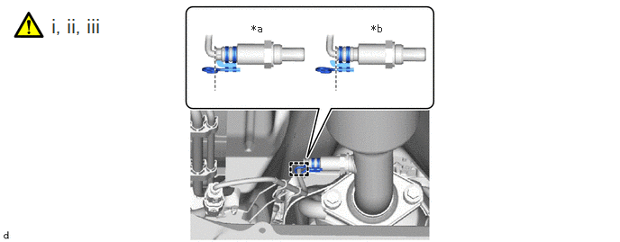
| *a | OK | *b | NG |
Install the wire harness clamp bracket to the No. 2 air fuel ratio sensor.
- NOTICE:
-
Aline the edge of the wire harness clamp bracket and No. 2 air fuel ratio sensor as shown in the illustration.
Engage the guide to connect the wire harness to the wire harness clamp bracket.
57543C
3.INSTALL CENTER NO. 1 FLOOR BRACE (for TMMF Made)
51447D
4.INSTALL CENTER NO. 4 ENGINE UNDER COVER
5.INSPECT FOR EXHAUST GAS LEAK
6.PERFORM INITIALIZATION
Perform "Inspection After Repair" after replacing the No. 2 air fuel ratio sensor.
Click hereEngine / Hybrid System>M15A-FXE (ENGINE CONTROL)>SFI SYSTEM>INITIALIZATION