P910 HYBRID TRANSMISSION / TRANSAXLE SHIFT LEVER POSITION SENSOR INSTALLATION
CAUTION / NOTICE / HINT
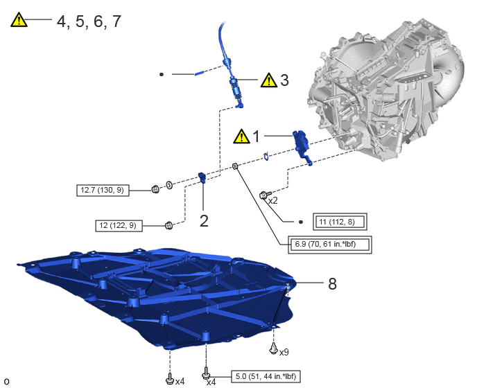
| Procedure | Part Name Code | 
|

|

|
|
|---|---|---|---|---|---|
| 1 | SHIFT LEVER POSITION SENSOR | 89451A | ( ) |
- | - |
| 2 | TRANSMISSION CONTROL LEVER | 35572D | - | - | - |
| 3 | TRANSMISSION CONTROL CABLE ASSEMBLY | 33820B | ()
|
- | - |
| 4 | INSPECT SHIFT LEVER POSITION SENSOR POSITION | - | ()
|
- | - |
| 5 | ADJUST SHIFT LEVER POSITION SENSOR POSITION | - | ()
|
- | - |
| 6 | INSPECT SHIFT LEVER POSITION | - | ()
|
- | - |
| 7 | ADJUST SHIFT LEVER POSITION | - | ()
|
- | - |
| 8 | NO. 1 ENGINE UNDER COVER ASSEMBLY | 51410 | - | - | - |

|
Tightening torque for "Major areas involving basic vehicle performance such as moving/turning/stopping" : N*m (kgf*cm, ft.*lbf) | 
|
N*m (kgf*cm, ft.*lbf): Specified torque |
| ● | Non-reusable part | - | - |
PROCEDURE

 89451A
1.INSTALL SHIFT LEVER POSITION SENSOR

Move the shift lever to N.
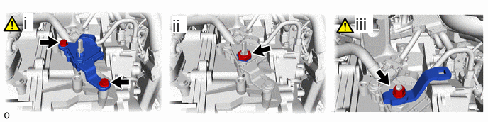
Temporarily install the shift lever position sensor to the hybrid vehicle transaxle assembly with 2 new bolts.
- NOTICE:
- ·
Do not reuse the shift lever position sensor if it has been dropped or subjected to a severe impact.
·Do not allow moisture to adhere to the connector terminal.
Install the lock plate to the shift lever position sensor with the lock nut.
- Torque:
- 6.9 N*m (70 kgf*cm, 61 in.*lbf)
Temporarily install the control shaft lever to the shift lever position sensor.
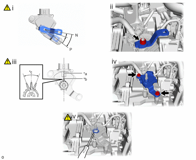
| *a | Neutral Basic Line | *b | Indicator |
| *c | Range of Play | - | - |
Turn the control shaft lever clockwise until it stops, then turn it counterclockwise 2 notches.
Remove the control shaft lever from the shift lever position sensor.
Align the indicator with the neutral basic line.
- NOTICE:
-
The indicator of the lock plate has a certain amount of play. Align the center point of the range of play with the neutral basic line.
Tighten the 2 bolts.
- Torque:
- 11 N*m (112 kgf*cm, 8 ft.*lbf)
Using a screwdriver with its tip wrapped with protective tape, secure the lock nut with the lock plate.
35572D
2.INSTALL TRANSMISSION CONTROL LEVER
- Torque:
- 12.7 N*m (130 kgf*cm, 9 ft.*lbf)
33820B
3.CONNECT TRANSMISSION CONTROL CABLE ASSEMBLY

Connect the transmission control cable assembly to the No. 1 transmission control cable bracket with a new clip.
Connect the transmission control cable assembly to the control shaft lever with the nut.
- Torque:
- 12 N*m (122 kgf*cm, 9 ft.*lbf)
4.INSPECT SHIFT LEVER POSITION SENSOR POSITION
5.ADJUST SHIFT LEVER POSITION SENSOR POSITION
6.INSPECT SHIFT LEVER POSITION
for TMMF Made: Click hereDrivetrain>P910 (HYBRID TRANSMISSION / TRANSAXLE)>SHIFT LEVER (for TMMF Made)>ON-VEHICLE INSPECTION
7.ADJUST SHIFT LEVER POSITION
51410
8.INSTALL NO. 1 ENGINE UNDER COVER ASSEMBLY