1NZ-FE INTAKE / EXHAUST EXHAUST PIPE INSTALLATION
PROCEDURE

 17408
1.INSTALL TAIL EXHAUST PIPE BAFFLE SUB-ASSEMBLY (w/ Side Mudguard)
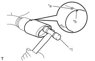
Align the keyway on a new tail exhaust pipe baffle sub-assembly with the protruding part of the exhaust tail pipe as shown in the illustration.
| *1 | Plastic Hammer |
| *a | Protruding Part |
| *b | Keyway |
Using a plastic hammer, uniformly tap in the tail exhaust pipe baffle sub-assembly.
17451
2.INSTALL EXHAUST PIPE GASKET
17410
3.INSTALL FRONT EXHAUST PIPE ASSEMBLY
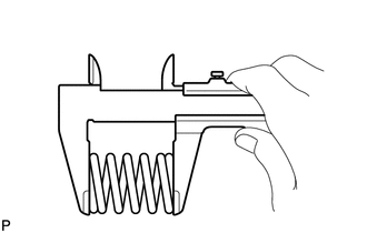
Using a vernier caliper, measure the free length of the compression springs.
- Minimum length:
41.5 mm (1.634 in.)
If the length is not as specified, replace the compression spring.
Hang the front exhaust pipe assembly with the 3 exhaust pipe supports.
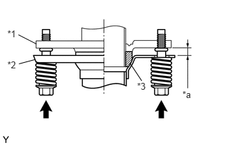
Install the front exhaust pipe sub-assembly onto the exhaust manifold converter sub-assembly with the 2 compression springs and 2 bolts.
| *1 | Exhaust Manifold |
| *2 | Front Exhaust Pipe Assembly |
| *3 | Gasket |
| *a | Space between flanges: 8.5 mm (0.335 in.) |
- Torque:
- 43 N*m (438 kgf*cm, 32 ft.*lbf)
- HINT:
-
After the installation, check that the gaps between the flanges of the exhaust manifold converter sub-assembly and front exhaust pipe assembly are consistent front-to-rear and left-to-right.
17451A
4.INSTALL NO. 2 EXHAUST PIPE GASKET
17430
5.INSTALL TAIL EXHAUST PIPE ASSEMBLY
Using a vernier caliper, measure the free length of the compression springs.
- Minimum length:
38.5 mm (1.516 in.)
If the length is not as specified, replace the compression spring.
Hang the front exhaust pipe assembly with the 2 exhaust pipe supports.
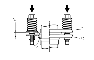
Install the tail exhaust pipe assembly onto the front exhaust pipe assembly with the 2 compression springs and 2 bolts.
| *1 | Front Exhaust pipe Assembly |
| *2 | Tail Exhaust Pipe Assembly |
| *3 | Gasket |
| *a | Space between flanges: 6.5 mm (0.256 in.) |
- Torque:
- 43 N*m (438 kgf*cm, 32 ft.*lbf)
- HINT:
-
After the installation, check that the gaps between the flanges of the exhaust manifold converter sub-assembly and front exhaust pipe assembly are consistent front-to-rear and left-to-right.
57533B
6.INSTALL FRONT FLOOR CENTER BRACE (w/ Side Mudguard)
89465A
7.INSTALL HEATED OXYGEN SENSOR (for Sensor 2)
8.INSPECT FOR EXHAUST GAS LEAK