C54 MANUAL TRANSMISSION / TRANSAXLE TRANSMISSION CONTROL CABLE INSTALLATION
PROCEDURE

 33820B
1.INSTALL TRANSMISSION CONTROL CABLE ASSEMBLY
Install the transmission control cable assembly with the 3 nuts.
- Torque:
- 5.0 N*m (51 kgf*cm, 44 in.*lbf)
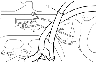
Pass the transmission control cable assembly under the transmission control cable support.
| *1 | Transmission Control Cable Assembly |
| *2 | Transmission Control Cable Support |
- NOTICE:
-
Do not pass the transmission control cable assembly between the transmission control cable support and dash panel.
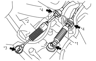
Install the control select cable and the control shift cable to the control cable bracket the 2 new clips B.
| *1 | Control Shift Cable |
| *2 | Control Select Cable |
| *3 | Clip A |
| *4 | Clip B |
Install the control select cable and the control shift cable to manual transaxle assembly with the 2 clips A and 2 washers.
33820B
2.CONNECT TRANSMISSION CONTROL CABLE ASSEMBLY
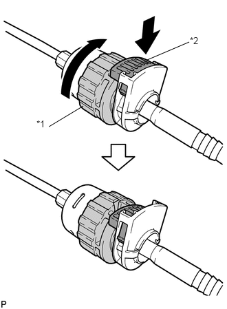
Rotate the transmission control cable nut counterclockwise 180° and push in the lock while holding the nut.
| *1 | Nut |
| *2 | Lock |
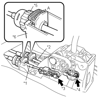
Install the control select cable and the control shift cable to the shift lever plate.
| *1 | Control Select Cable |
| *2 | Control Shift Cable |
| *3 | Clip A |
| *4 | Clip B |
| *5 | Nut |
| *6 | Shift Lever Plate |
- NOTICE:
-
After installation, check that the cable outer lock extends past the line A-A, as shown in the diagram.
Connect the control shift cable to the floor shift shift lever assembly with the clip B.
Connect the control select cable to the floor shift shift lever assembly with the clip A.
- NOTICE:
-
Install the cable end adjustment mechanism so that the lock faces the driver seat.
33820B
3.ADJUST TRANSMISSION CONTROL CABLE ASSEMBLY
58151
4.INSTALL FRONT NO. 1 FLOOR HEAT INSULATOR
Install the front No. 1 floor heat insulator with the 2 bolts and nut.
- Torque:
- 5.5 N*m (56 kgf*cm, 49 in.*lbf)
17451
5.INSTALL EXHAUST PIPE GASKET
17451A
6.INSTALL NO. 2 EXHAUST PIPE GASKET
17410
7.INSTALL FRONT EXHAUST PIPE ASSEMBLY
57533B
8.INSTALL FRONT FLOOR CENTER BRACE (w/ Side Mudguard)
9.INSTALL AIR CLEANER CAP SUB-ASSEMBLY WITH NO. 1 AIR CLEANER HOSE
58910C
10.INSTALL REAR CONSOLE BOX ASSEMBLY
11.INSPECT FOR EXHAUST GAS LEAK