REAR SUSPENSION REAR AXLE BEAM REMOVAL
PROCEDURE

 1.REMOVE REAR WHEEL
2.DRAIN BRAKE FLUID
- NOTICE:
-
Immediately wash off any brake fluid that comes into contact with any painted surfaces.
89516D
3.SEPARATE SKID CONTROL SENSOR WIRE LH (w/ ABS)
89516C
4.SEPARATE SKID CONTROL SENSOR WIRE RH (w/ ABS)
- HINT:
-
Use the same procedure for the RH side as for the LH side.
47324
5.SEPARATE NO. 4 REAR BRAKE TUBE
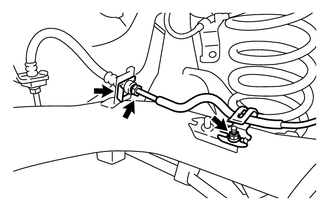
Using a union nut wrench (10 mm), separate the No. 4 rear brake tube while holding the rear flexible hose LH with a wrench.
Remove the clip and disconnect the rear flexible hose LH from the rear axle beam assembly.
Remove the nut and separate the No. 4 rear brake tube.
47323
6.SEPARATE NO. 3 REAR BRAKE TUBE
- HINT:
-
Use the same procedure for the RH side as for the LH side.
46430
7.SEPARATE NO. 3 PARKING BRAKE CABLE ASSEMBLY
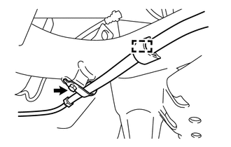
Remove the cable clamp from the rear axle beam assembly.
Remove the bolt and separate the No. 3 parking brake cable assembly.
Remove the cable clamp from the No. 3 parking brake cable assembly.
- HINT:
-
Replace the clamp with a new one when installing the No. 3 parking brake cable assembly.
46420
8.SEPARATE NO. 2 PARKING BRAKE CABLE ASSEMBLY
- HINT:
-
Use the same procedure for the RH side as for the LH side.
42403
9.REMOVE REAR BRAKE DRUM SUB-ASSEMBLY
42450B
10.REMOVE REAR AXLE HUB AND BEARING ASSEMBLY
42110F
11.LOOSEN REAR AXLE BEAM ASSEMBLY
48540
12.SEPARATE REAR SHOCK ABSORBER ASSEMBLY LH
48530
13.SEPARATE REAR SHOCK ABSORBER ASSEMBLY RH
- HINT:
-
Use the same procedure for the RH side as for the LH side.
48231B
14.REMOVE REAR COIL SPRING LH
48231A
15.REMOVE REAR COIL SPRING RH
- HINT:
-
Use the same procedure for the RH side as for the LH side.
42110F
16.REMOVE REAR AXLE BEAM ASSEMBLY
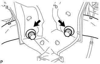
Remove the 2 bolts and rear axle beam assembly.
| *a | RH Side |
| *b | LH Side |
48725G
17.REMOVE REAR AXLE CARRIER BUSH LH
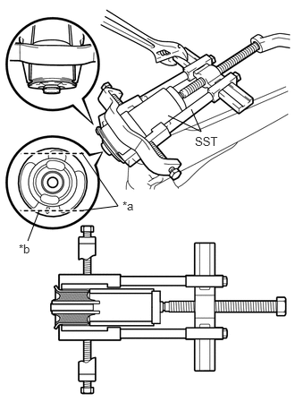
| *a | Bend Portions |
| *b | Bush Mark |
Place a matchmark on the rear axle beam assembly with it aligned with the bush mark.
Using a chisel and hammer, bend the 2 portions of the bush rib.
- NOTICE:
-
Bend the bush rib until the claw of SST can be suspended.
Using SST, remove the rear axle carrier bush LH from the rear axle beam assembly.
- SST
- 09950-40011 (09951-04020, 09952-04010, 09953-04030, 09954-04020, 09955-04051, 09957-04010, 09958-04011)
09710-30041 (09710-03221)
09950-60010 (09951-00590)
- NOTICE:
-
Apply paint to any scratches on the rear axle beam assembly.
48725F
18.REMOVE REAR AXLE CARRIER BUSH RH
- HINT:
-
Use the same procedure for the RH side as for the LH side.