AUDIO / VIDEO AUDIO AND VISUAL SYSTEM(for Radio and Display Type) Reverse Signal Circuit
DESCRIPTION
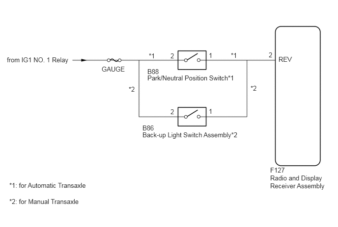
The radio and display receiver assembly receives a reverse signal from the park/neutral position switch assembly*1 or back-up light switch assembly*2 to use for adjusting the vehicle position on the multi-display.
*1: except Manual Transaxle
*2: for Manual Transaxle
WIRING DIAGRAM
PROCEDURE
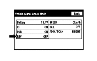
Enter the "Vehicle Signal Check Mode" screen. [Refer to Check Vehicle Signal in Operation Check (See page Audio / Visual / Telematics>AUDIO / VIDEO>AUDIO AND VISUAL SYSTEM(for Radio and Display Type)>OPERATION CHECK)]
Check that the display changes between ON and OFF according to the shift lever position.
- OK:
Shift Lever Position Display R ON Except R OFF
- HINT:
-
This display is updated once per second. As a result, it is normal for the display to lag behind the actual shift lever position.
OK
NG
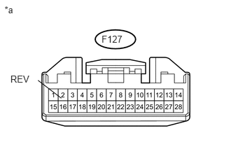
Disconnect the radio and display receiver assembly connector.
Measure the voltage according to the value(s) in the table below.
- Standard Voltage:
Tester Connection Switch Condition Specified Condition F127-2 (REV) - Body ground Ignition switch ON, shift lever in R 7.5 to 14 V F127-2 (REV) - Body ground Ignition switch ON, shift lever not in R Below 1 V
| *a | Front view of wire harness connector
(to Radio and Display Receiver Assembly) |
| Result | Proceed to |
|---|---|
| OK | A |
| NG (for Automatic Transaxle) | B |
| NG (for Manual Transaxle) | C |
A
B
C
Disconnect the F127 radio and display receiver assembly connector.
Disconnect the B88 park/neutral position switch connector.
Measure the resistance according to the value(s) in the table below.
- Standard Resistance:
Tester Connection Condition Specified Condition F127-2 (REV) - B88-2 Always Below 1 Ω F127-2 (REV) - Body ground Always 10 kΩ or higher
| Result | Proceed to |
|---|---|
| NG | A |
| OK (for U340E) | B |
| OK (for U441E) | C |
A
B
(See pageDrivetrain>U340E (AUTOMATIC TRANSMISSION / TRANSAXLE)>PARK / NEUTRAL POSITION SWITCH>REMOVAL)
C
(See pageDrivetrain>U441E (AUTOMATIC TRANSMISSION / TRANSAXLE)>PARK / NEUTRAL POSITION SWITCH>REMOVAL)
Disconnect the F127 radio and display receiver assembly connector.
Disconnect the B86 back-up light switch assembly connector.
Measure the resistance according to the value(s) in the table below.
- Standard Resistance:
Tester Connection Condition Specified Condition F127-2 (REV) - B86-1 Always Below 1 Ω F127-2 (REV) - Body ground Always 10 kΩ or higher
OK
NG