POWER DISTRIBUTION MAIN BODY ECU INSTALLATION
PROCEDURE

 89221
1.INSTALL MAIN BODY ECU
- NOTICE:
- ·
Make sure that there is no foreign matter in the engaging part.
·Do not touch the connector.
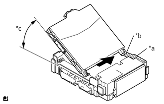
Contact the main body ECU guide against the housing side wall.
| *a | Housing Side Wall |
| *b | Guide |
| *c | 20° or more |
- HINT:
-
The angle between the junction block and the main body ECU guide should be 20° or more.
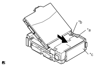
While aligning the guide with the housing side wall, slide the main body ECU toward the fuse area of the instrument panel junction block.
| *a | Housing Side Wall |
| *b | Guide |
| *c | Fuse Area |
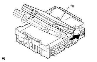
Slide the main body ECU until it contacts the A surface.
- NOTICE:
- ·
Slide the main body ECU gently.
·Do not apply strong impact to the side of the main body ECU.
| *a | A surface |
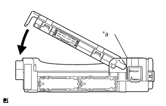
Rotate the main body ECU while holding it against the junction block A surface (axis of rotation).
| *a | A surface |
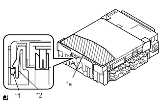
Rotate the main body ECU until it engages with the lock to install it.
| *1 | Main Body ECU |
| *2 | Instrument Panel Junction Block |
| *a | Push Area |
- NOTICE:
- ·
When pressing the main body ECU, press the push area as shown in the illustration.
·A lock sound will be heard when the main body ECU is engaged.
·Do not hit or weight the main body ECU when it engages with the instrument panel junction block.
- HINT:
-
If a lock sound is not heard, visually check the lock engagement. Check that the height of the main body ECU and instrument panel junction block match.
2.INSTALL JUNCTION BLOCK BRACKET
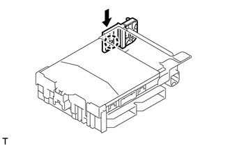
Engage the claw and install the junction block bracket.
3.INSTALL JUNCTION BLOCK BRACKET
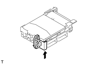
Engage the claw and install the junction block bracket.
82730
4.INSTALL INSTRUMENT PANEL JUNCTION BLOCK ASSEMBLY
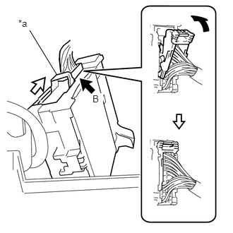
Connect the back side connector B indicated as shown in the illustration.
Slide the lever by the arrow indicated as shown in the illustration.
| *a | Lever |
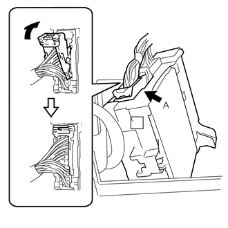
Connect the back side connector A indicated as shown in the illustration.
Engage the claw, 2 clamps and install the instrument panel junction block.
Tighten the 2 bolts.
- Torque:
- 8.4 N*m (86 kgf*cm, 74 in.*lbf)
Connect the main body ECU connector.
Connect the connectors to front side of the instrument panel junction block.
Engage the clamps.
82141
5.INSTALL INSTRUMENT PANEL WIRE
Engage the clamp and install the instrument panel wire.
Tighten the screw.
55433B
6.INSTALL LOWER NO. 2 INSTRUMENT PANEL FINISH PANEL (for LHD)
55302A
7.INSTALL UPPER INSTRUMENT PANEL SUB-ASSEMBLY (for LHD)
55550
8.INSTALL GLOVE COMPARTMENT DOOR ASSEMBLY (for RHD)