INTERIOR PANELS / TRIM LOWER INSTRUMENT PANEL INSTALLATION
PROCEDURE

 55303B
1.INSTALL LOWER INSTRUMENT PANEL SUB-ASSEMBLY
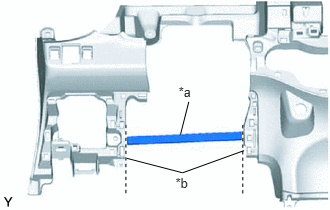
Using a nipper, cut off both ends of the runner portion shown in the illustration (When installing a new one).
| *a | Runner Portion |
| *b | Cut Off |
Engage the 10 guides and install the lower instrument panel.
Install the lower instrument panel with the 6 <B> or <C> bolts, <D> or <E> screw, 2 <F> or <H> or <I> bolts and bolt.
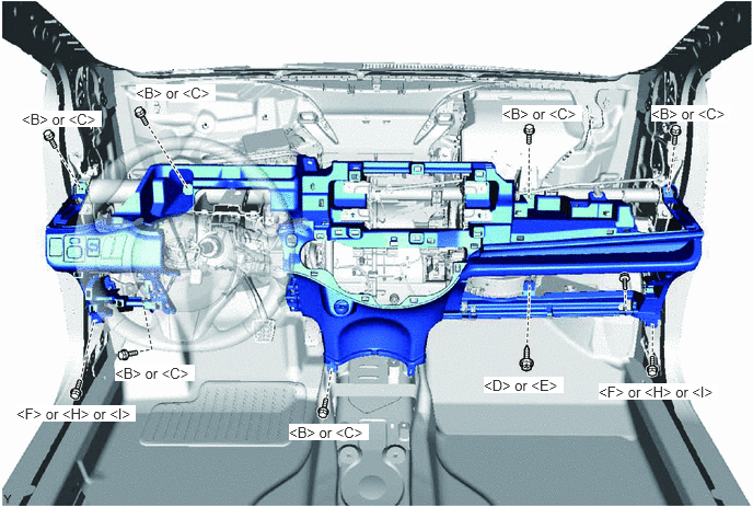
Connect the clamps and connectors.
Engage the 2 claws and install the DLC3 connector.
53601
2.INSTALL HOOD LOCK CONTROL LEVER SUB-ASSEMBLY
Engage the 3 claws and install the hood lock control lever.
58910C
3.INSTALL REAR CONSOLE BOX ASSEMBLY
55900
4.INSTALL AIR CONDITIONING CONTROL ASSEMBLY (for Automatic Air Conditioning System)
55909A
5.CONNECT AIR MIX DAMPER CONTROL CABLE SUB-ASSEMBLY (for Manual Air Conditioning System)
55908A
6.CONNECT AIR INLET DAMPER CONTROL CABLE SUB-ASSEMBLY (for Manual Air Conditioning System)
55906A
7.CONNECT DEFROSTER DAMPER CONTROL CABLE SUB-ASSEMBLY (for Manual Air Conditioning System)
8.INSTALL AIR CONDITIONING PANEL ASSEMBLY (for Manual Air Conditioning System)
55521C
9.INSTALL STEREO OPENING COVER WITH BRACKET (w/o Radio Receiver)
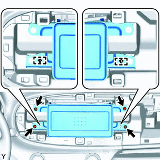
Align the 2 holes in the radio bracket with the 2 bosses of the instrument panel.
Install the radio stereo opening cover with bracket with the 4 screws.
10.INSTALL RADIO RECEIVER ASSEMBLY WITH BRACKET (w/ Radio Receiver)
55432B
11.INSTALL LOWER INSTRUMENT PANEL FINISH PANEL (w/o Knee Airbag)
for LHD:
Engage the 5 claws and 2 clips and install the instrument panel finish panel.
for RHD:
Engage the 6 claws and 2 clips and install the instrument panel finish panel.
73900
12.INSTALL LOWER NO. 1 INSTRUMENT PANEL AIRBAG ASSEMBLY (w/ Knee Airbag)
55433B
13.INSTALL LOWER NO. 2 INSTRUMENT PANEL FINISH PANEL (for LHD)
Engage the 2 claws and 5 clips and install the instrument panel finish panel.
55606
14.INSTALL NO. 1 INSTRUMENT PANEL UNDER COVER SUB-ASSEMBLY
Engage the guide and the claw.
Install the instrument panel under cover with the 2 <A> screws.
55607
15.INSTALL NO. 2 INSTRUMENT PANEL UNDER COVER SUB-ASSEMBLY
Engage the guide and the 3 claws and install the instrument panel under cover.
55550
16.INSTALL GLOVE COMPARTMENT DOOR ASSEMBLY
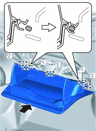
Engage the 3 guides and 2 hinges in the horizontal direction to install the glove compartment door.
| *1 | Hinge |
| *2 | Guide |
- NOTICE:
-
Engage the 2 hinges in the horizontal direction, otherwise, installation failure caused by excessive play around the hinges will result.
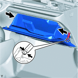
While pushing in the sides of the glove compartment door as indicated by the arrows in the illustration, close the door to engage it to the 2 stoppers.
Engage the claw and connect the glove compartment door stopper.
55302A
17.INSTALL UPPER INSTRUMENT PANEL SUB-ASSEMBLY