BLOWER UNIT (for Sedan) > INSTALLATION |
| 1. INSTALL BLOWER UNIT |
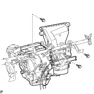
Install the blower unit with the 3 screws.
| 2. INSTALL INSTRUMENT PANEL REINFORCEMENT |
|
Temporarily tighten the air conditioning unit with the 3 screws.
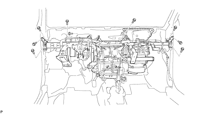
Install the instrument panel reinforcement together with the air conditioning unit with the 9 bolts.
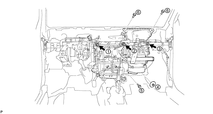
Tighten the temporarily 3 screws, the 3 bolts and the nut in the sequence shown in the illustration.
Install the wire harness with the clamps and connect the connectors.
Engage the clamps.
Connect the connectors.
Install the ground wire with the bolt.
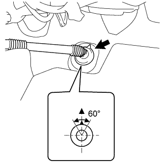 |
Install the drain hose into the position shown in the illustration.
| 3. INSTALL CONNECTOR NO. 2 HOLDER |
Connect the connectors.
Install the connector No. 2 holder with the bolt.
| 4. INSTALL MAIN BODY ECU (DRIVER SIDE JUNCTION BLOCK) |
Install the main body ECU with the 2 bolts.
Connect the 5 connectors and the 3 clamps.
| 5. INSTALL INSTRUMENT PANEL BRACE SUB-ASSEMBLY |
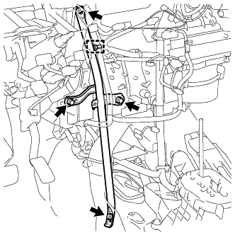 |
Install the instrument panel brace sub-assembly with the bolt, screw and nut.
Engage the clamp.
| 6. INSTALL DEFROSTER NOZZLE ASSEMBLY |
Engage the 5 claws to install the defroster nozzle assembly.
Connect the 3 clamps and connector and install the wire harness.
| 7. INSTALL HEATER TO REGISTER DUCT ASSEMBLY |
Engage the 3 claws to install the heater to register duct assembly.
| 8. INSTALL STEERING COLUMN ASSEMBLY |
| 9. INSTALL LOWER INSTRUMENT PANEL SUB-ASSEMBLY |
| 10. CONNECT HEATER WATER INLET HOSE |
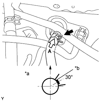 |
Connect the heater water inlet hose onto the heater unit.
| *a | View A |
| *b | White Paint Mark |
| 11. CONNECT HEATER WATER OUTLET HOSE |
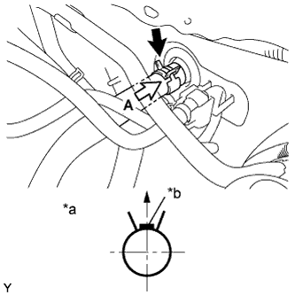 |
Connect the heater water outlet hose onto the heater unit.
| *a | View A |
| *b | Purple Paint Mark |
| 12. INSTALL LIQUID TUBE SUB-ASSEMBLY |
Remove the vinyl tape from the liquid tube sub-assembly and the connecting portion of the unit.
Apply sufficient compressor oil (ND-OIL8) to a new O-ring and the connecting part of the liquid tube sub-assembly.
Install the O-ring onto the liquid tube sub-assembly.
Connect the liquid tube sub-assembly to the unit .
| 13. INSTALL SUCTION TUBE SUB-ASSEMBLY |
Remove the vinyl tape from the suction tube sub-assembly and the connecting part of the unit.
Apply sufficient compressor oil (ND-OIL8) to a new O-ring and the connecting part of the suction tube sub-assembly.
Install the O-ring onto the suction tube sub-assembly.
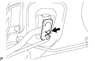 |
Insert the hook type connector securely into the fitting holes and tighten the bolt.
| 14. ADD ENGINE COOLANT |
Tighten the radiator drain cock plug by hand.
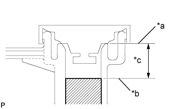 |
Slowly fill the radiator with TOYOTA Super Long Life Coolant (SLLC) from the water filler. (Coolant level should be within 20 mm (0.787 in.) from the filler tube end.)
| *a | Filler Tube End |
| *b | Coolant Level |
| *c | 20 mm (0.787 in.) |
| Transaxle Type | Coolant Capacity |
| Automatic Transaxle | 4.7 liters (5.0 US qts, 4.4 Imp. qts) |
| Manual Transaxle | 4.8 liters (5.1 US qts, 4.5 Imp. qts) |
Remove the reserve tank cap.
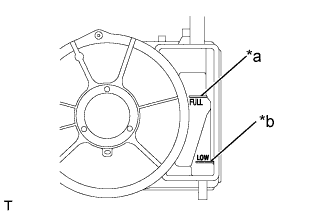 |
Slowly pour coolant into the radiator reserve tank assembly until it reaches the full line.
| *a | Full Line |
| *b | Low Line |
Install the water filler cap sub-assembly securely.
Install the reserve tank cap.
Bleed air from the cooling system.
Warm up the engine until the thermostat opens.
While the thermostat is open, circulate the coolant for several minutes.
Stop the engine and wait until the coolant cools down.
Recheck the coolant level inside the radiator reserve tank assembly. If it is below the full level, add coolant.
| 15. CONNECT CABLE TO NEGATIVE BATTERY TERMINAL |
| 16. CHECK SRS WARNING LIGHT |
| 17. CHARGE REFRIGERANT |
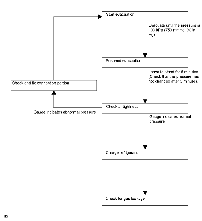
Perform vacuum purging using a vacuum pump.
Charge refrigerant HFC-134a (R134a).
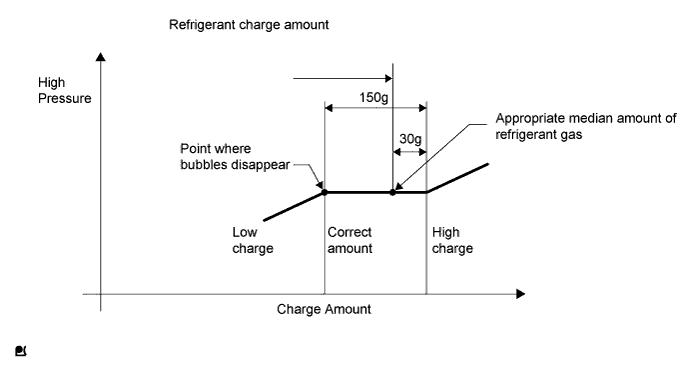
Install the caps onto the service valves on the refrigerant line.
| 18. WARM UP ENGINE |
| 19. INSPECT FOR ENGINE COOLANT LEAK |
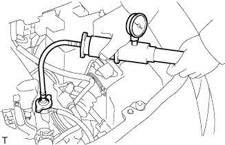 |
Fill the radiator assembly with engine coolant, and attach a radiator cap tester.
Pump the tester to 118 kPa (1.2 kgf/cm2, 17.1 psi), and then check that the pressure does not drop.
If the pressure drops, check the hoses, radiator assembly and water pump assembly for leaks. If there are no signs or traces of external engine coolant leaks, check the heater core, cylinder block and head.
| 20. INSPECT FOR REFRIGERANT LEAK |
After recharging the refrigerant gas, check for refrigerant gas leakage using a halogen leak detector.
Perform the operation as follows:
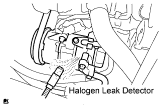 |
Using the halogen leak detector, check the refrigerant line, especially the connection points, for leakage.
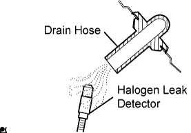 |
Bring the halogen leak detector close to the drain hose before performing the test.
If a gas leak is not detected from the drain hose, remove the blower motor from the cooling unit. Insert the halogen leak detector sensor into the unit and perform the test.
Disconnect the pressure switch connector and leave it for approximately 20 minutes. Bring the halogen leak detector close to the pressure switch and perform the test.
| 21. POSITION FRONT WHEELS FACING STRAIGHT AHEAD |
| 22. PERFORM CALIBRATION OF TORQUE SENSOR ZERO POINT |