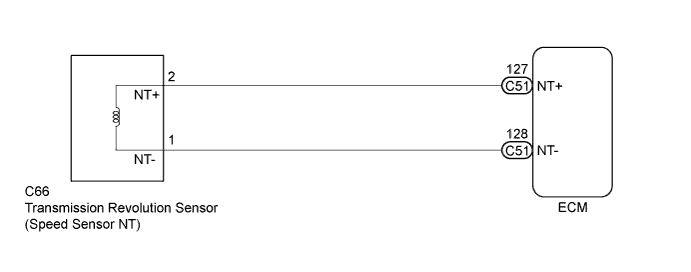
DTC P0717 Turbine Speed Sensor Circuit No Signal |
| DTC No. | DTC Detection Condition | Trouble Area |
| P0717 | All conditions below are detected for 5 seconds or more (1 trip detection logic). (a) Gear change is not being performed. (b) Gear position: 3rd or 4th. (c) T/M input shaft rpm: Less than 300 rpm. (d) T/M output shaft rpm: 1000 rpm or more. (e) Park/neutral position switch (NSW, R and L) is OFF. (f) Shift solenoid valves, park/neutral position switch and vehicle speed sensor are in normal operation. |
|
| Related DTCs | P0717: Turbine speed sensor/Verify pulse input |
| Required sensors/Components | Transmission revolution sensor (Speed sensor NT) |
| Frequency of operation | Continuous |
| Duration | 5 seconds |
| MIL operation | Immediate |
| Sequence of operation | None |
| Shift change | After shift change is completed and before starting next shift change operation |
| ECM selected gear | 3rd or 4th |
| Output shaft revolution | 1000 rpm or more |
| Park/neutral position switch | OFF |
| R switch | OFF |
| L switch | OFF |
| Transmission range switch fail (P0705) | Not detected |
| Battery voltage | 8 V or more |
| Ignition switch | ON |
| Starter | OFF |
| Engine | Running |
| Turbine speed sensor revolution | Less than 300 rpm |
| Transmission revolution sensor (Speed sensor NT) | Input turbine speed is equal to engine speed when lock-up ON |
| 1.INSPECT TRANSMISSION REVOLUTION SENSOR INSTALLATION |
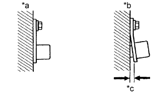 |
Check the transmission revolution sensor installation.
| *a | Correct |
| *b | Incorrect |
| *c | Clearance |
|
| ||||
| OK | |
 |
| 2.INSPECT TRANSMISSION REVOLUTION SENSOR |
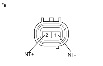 |
Disconnect the C66 transmission revolution sensor connector.
Measure the resistance according to the value(s) in the table below.
| Tester Connection | Condition | Specified Condition |
| 1 (NT-) - 2 (NT+) | 20°C (68°F) | 560 to 680 Ω |
| *a | Component without harness connected (Transmission Revolution Sensor) |
|
| ||||
| OK | |
|
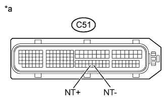
| 3.CHECK HARNESS AND CONNECTOR (TRANSMISSION REVOLUTION SENSOR - ECM) |
 |
Connect the C66 transmission revolution sensor connector.
Disconnect the ECM connector.
Measure the resistance according to the value(s) in the table below.
| Tester Connection | Condition | Specified Condition |
| C51-127 (NT+) - C51-128 (NT-) | 20°C (68°F) | 560 to 680 Ω |
| C51-127 (NT+) - Body ground | Always | 10 kΩ or higher |
| C51-128 (NT-) - Body ground | Always | 10 kΩ or higher |
| *a | Front view of wire harness connector (to ECM) |
|
| ||||
| OK | ||
 | ||
| ||
