 |
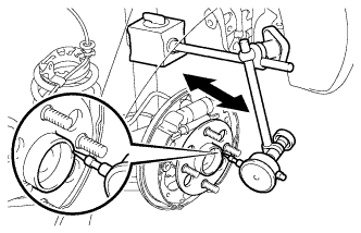
Using a dial indicator, check the backlash near the center of the axle hub.
- Maximum:
- 0.05 mm (0.00197 in.)
REAR SPEED SENSOR (for Hatchback) > INSTALLATION |
| 1. INSTALL REAR AXLE HUB AND BEARING ASSEMBLY (for Rear Drum Brake) |
Install the axle hub and bearing assembly onto the axle beam with the 4 bolts.
| 2. INSTALL REAR AXLE HUB AND BEARING ASSEMBLY (for Rear Disc Brake) |
Install the axle hub and bearing assembly and disc brake dust cover sub-assembly onto the axle beam with the 4 bolts.
| 3. INSPECT REAR AXLE HUB BEARING BACKLASH (for Rear Drum Brake) |
|
Using a dial indicator, check the backlash near the center of the axle hub.
| 4. INSPECT REAR AXLE HUB BEARING BACKLASH (for Rear Disc Brake) |
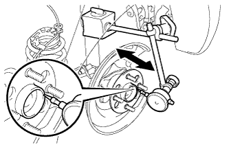 |
Using a dial indicator, check the backlash near the center of the axle hub.
| 5. INSPECT REAR AXLE HUB RUNOUT (for Rear Drum Brake) |
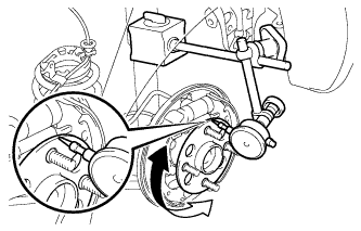 |
Using a dial indicator, check the runout of the surface of the axle hub.
| 6. INSPECT REAR AXLE HUB RUNOUT (for Rear Disc Brake) |
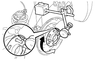 |
Using a dial indicator, check the runout of the surface of the axle hub.
| 7. CONNECT SKID CONTROL SENSOR WIRE (w/ ABS) |
Connect the skid control sensor wire connector.
| 8. INSTALL REAR BRAKE DRUM SUB-ASSEMBLY (for Rear Drum Brake) |
| 9. ADJUST REAR DRUM BRAKE SHOE CLEARANCE (for Rear Drum Brake) |
Provisionally install the hub nuts.
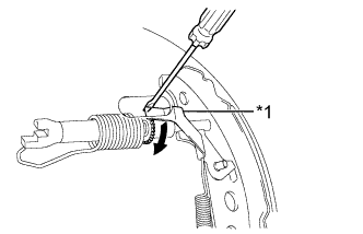 |
Remove the hole plug, and turn the adjuster to expand the shoe until the drum locks.
| *1 | Automatic Adjust Lever |
 | Expand |
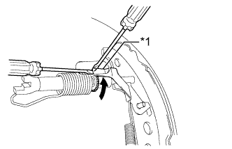 |
Hold the automatic adjust lever away from the adjuster, and contract the brake shoe by turning the adjust bolt using another screwdriver until the drum can rotate smoothly.
| *1 | Automatic Adjust Lever |
| Contract |
Install the hole plug.
| 10. INSTALL REAR DISC (for Rear Disc Brake) |
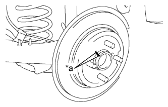 |
Align the matchmarks of the rear disc and axle hub and install the rear disc.
| *a | Matchmark |
| 11. INSTALL REAR DISC BRAKE CYLINDER ASSEMBLY (for Rear Disc Brake) |
Install the rear disc brake cylinder assembly onto the axle beam with the 2 bolts.
| 12. INSTALL NO. 3 PARKING BRAKE CABLE ASSEMBLY (for Rear Disc Brake) |
Insert the parking brake cable into the disc brake cylinder and engage the clip claws of the parking brake cable to the rear disc brake cylinder guide.
Connect the cable end to the rear disc brake cylinder operation lever.
| 13. INSTALL REAR WHEEL |
| 14. INSPECT AND ADJUST PARKING BRAKE LEVER TRAVEL (for Rear Disc Brake) |
| 15. INSPECT REAR WHEEL ALIGNMENT |
| 16. INSTALL REAR CONSOLE BOX ASSEMBLY |
| 17. CHECK ABS SENSOR SIGNAL (w/o VSC) |
| 18. CHECK VSC SENSOR SIGNAL (w/ VSC) |