 |
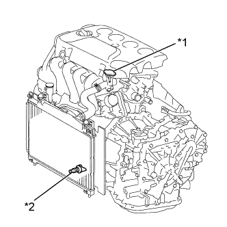
Loosen the radiator drain cock plug.
| *1 | Water Filler Cap Sub-assembly |
| *2 | Radiator Drain Cock Plug |
CYLINDER HEAD GASKET (for Hatchback) > REMOVAL |
| 1. DISCHARGE FUEL SYSTEM PRESSURE |
| 2. REMOVE FRONT WHEEL RH |
| 3. REMOVE ENGINE UNDER COVER RH |
| 4. DRAIN ENGINE OIL |
Remove the oil filler cap sub-assembly.
Remove the oil pan drain plug and the gasket from the No. 2 oil pan sub-assembly, and drain the engine oil into a container.
Clean and install the oil pan drain plug with a new gasket to the No. 2 oil pan sub-assembly.
| 5. DRAIN ENGINE COOLANT |
|
Loosen the radiator drain cock plug.
| *1 | Water Filler Cap Sub-assembly |
| *2 | Radiator Drain Cock Plug |
Remove the water filler cap sub-assembly, then drain coolant.
| 6. DISCONNECT CABLE FROM NEGATIVE BATTERY TERMINAL |
| 7. REMOVE WINDSHIELD WIPER MOTOR AND LINK ASSEMBLY |
| 8. REMOVE FRONT NO. 1 VENTILATOR SEAL |
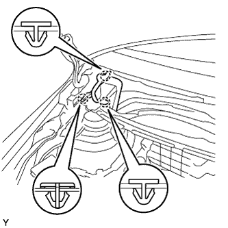 |
Disengage the 3 claws and remove the front air shutter seal RH.
| 9. REMOVE FRONT AIR SHUTTER SEAL RH |
| 10. REMOVE INNER COWL TOP TO COWL BRACE |
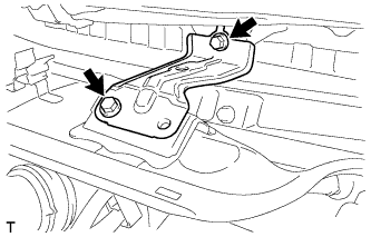 |
Remove the 2 bolts and the inner cowl top to cowl brace.
| 11. REMOVE OUTER COWL TOP PANEL |
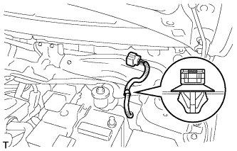 |
Disengage the wire harness clamp.
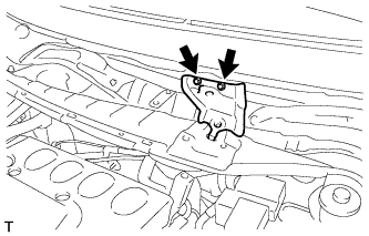 |
Remove the 2 bolts and remove the cowl top to cowl inner brace.
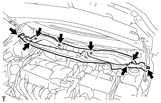 |
Remove the 8 bolts and remove the cowl top panel outer.
| 12. REMOVE BATTERY |
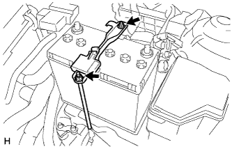 |
Disconnect the battery terminal.
Remove the 2 nuts and the battery clamp.
Remove the battery.
| 13. REMOVE BATTERY TRAY |
| 14. REMOVE AIR CLEANER CAP SUB-ASSEMBLY WITH NO. 1 AIR CLEANER HOSE |
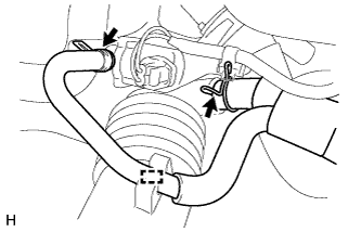 |
Disengage the clamp and disconnect the fuel vapor feed hose assembly from the No. 1 air cleaner hose.
Loosen the 2 hose clamps and disconnect the fuel vapor feed hose assembly from the No. 1 air cleaner hose and vacuum switching valve assembly.
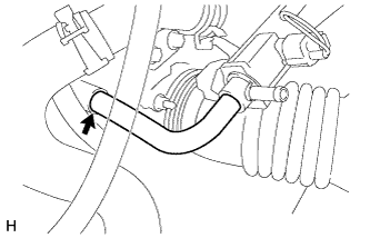 |
Disconnect the No. 2 fuel vapor feed hose from the intake manifold.
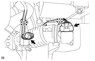 |
Disengage the 2 clamps and disconnect the wire harness from the air cleaner cap sub-assembly and vacuum switching valve assembly.
Disconnect the mass air flow meter connector.
Disconnect the vacuum switching valve connector.
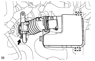 |
Loosen the hose clamp and disconnect the No. 1 air cleaner hose from the throttle with motor body assembly.
Disengage the 2 clamps and remove the air cleaner cap sub-assembly with No. 1 air cleaner hose.
| 15. REMOVE NO. 1 IGNITION COIL |
| 16. DISCONNECT NO. 3 RADIATOR HOSE |
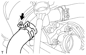 |
Disconnect No. 3 radiator hose.
| 17. DISCONNECT RESERVE TANK HOSE |
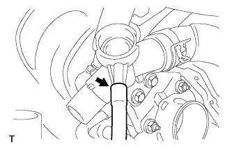 |
Disconnect the reserve tank hose.
| 18. REMOVE WATER FILLER SUB-ASSEMBLY |
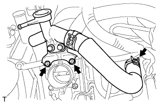 |
Separate No. 1 radiator hose from the cylinder head.
Remove the 2 nuts and the water filler sub-assembly.
| 19. DISCONNECT NO. 2 WATER BY-PASS HOSE |
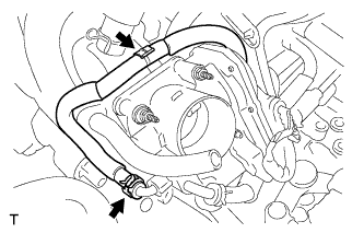 |
Disconnect No. 2 water by-pass hose.
| 20. DISCONNECT WATER BY-PASS HOSE |
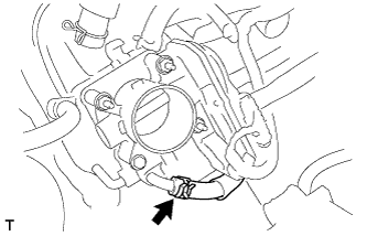 |
Disconnect the water by-pass hose.
| 21. DISCONNECT THROTTLE BODY ASSEMBLY CONNECTOR |
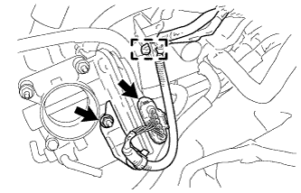 |
Disengage the clamp and disconnect the wire harness from the wire harness bracket.
Remove the nut and disconnect the wire harness from the throttle body assembly.
Disconnect the throttle body assembly connector.
| 22. DISCONNECT VENTILATION HOSE |
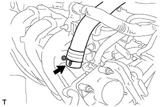 |
Disconnect the ventilation hose.
| 23. DISCONNECT UNION TO CONNECTOR TUBE HOSE |
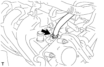 |
Disconnect the union to connector tube hose.
| 24. REMOVE OIL LEVEL DIPSTICK SUB-ASSEMBLY |
| 25. REMOVE INTAKE MANIFOLD |
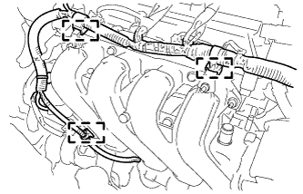 |
Disengage the 3 clamps and disconnect the wire harness from the intake manifold.
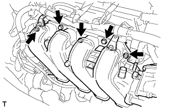 |
Remove the 3 bolts, 2 nuts and the intake manifold.
| 26. REMOVE OIL LEVEL DIPSTICK GUIDE |
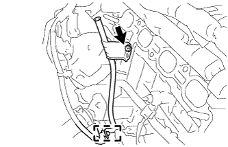 |
Disengage the clamp and disconnect the wire harness from the oil level dipstick guide.
Remove the bolt and the oil level dipstick guide.
Remove the O-ring from the oil level dipstick guide.
| 27. DISCONNECT FUEL TUBE SUB-ASSEMBLY |
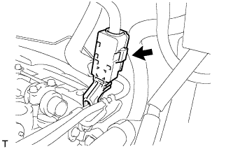 |
Remove the EFI fuel pipe clamp.
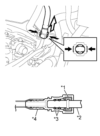 |
Pinch the retainer of the fuel tube connector, then pull the fuel tube connector to disconnect the fuel tube out of the fuel delivery pipe sub-assembly.
| *1 | Retainer |
| *2 | Fuel Pipe |
| *3 | O-Ring |
| *4 | Nylon Tube |
 | Pinch |
 | Pull |
| 28. DISCONNECT BOOSTER VACUUM TUBE |
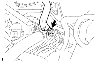 |
Disconnect the booster vacuum tube.
| 29. DISCONNECT CAMSHAFT POSITION SENSOR CONNECTOR |
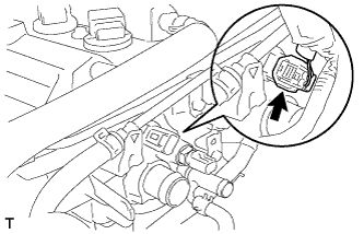 |
Disconnect the camshaft position sensor connector.
| 30. DISCONNECT ENGINE COOLANT TEMPERATURE SENSOR CONNECTOR |
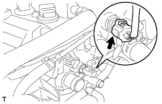 |
Disconnect the engine coolant temperature sensor connector.
| 31. DISCONNECT AIR FUEL RATIO SENSOR CONNECTOR |
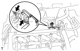 |
Remove the bolts and separate the sensor bracket.
Disconnect the air fuel ratio sensor connector.
| 32. DISCONNECT INLET HEATER WATER HOSE A |
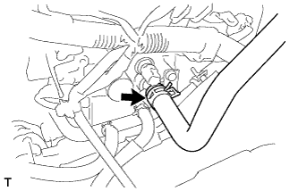 |
Disconnect heater water inlet hose A.
| 33. SEPARATE NO. 1 WATER BY-PASS PIPE |
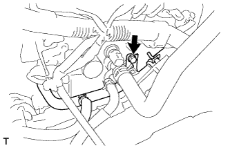 |
Remove the bolt and separate No. 1 water by-pass pipe.
| 34. DISCONNECT WIRE HARNESS |
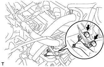 |
Remove the 2 bolts and disconnect the wire harness.
| 35. SEPARATE FRONT EXHAUST PIPE ASSEMBLY |
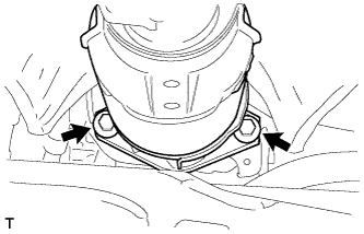 |
Remove the 2 bolts and 2 compression springs and separate the front exhaust pipe assembly.
| 36. REMOVE EXHAUST PIPE GASKET |
Remove the No. 2 exhaust pipe gasket from the front exhaust pipe assembly.
| 37. REMOVE MANIFOLD SUPPORT BRACKET |
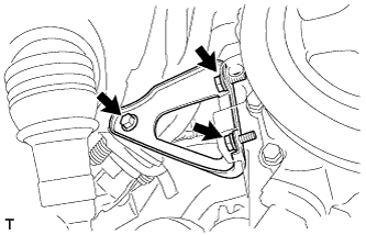 |
Remove the 3 bolts and the manifold support bracket.
| 38. REMOVE GENERATOR ASSEMBLY |
| 39. DISCONNECT VENTILATION HOSE |
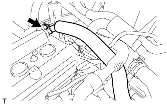 |
Disconnect the ventilation hose.
| 40. DISCONNECT FUEL VAPOR FEED HOSE ASSEMBLY |
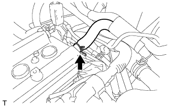 |
Disconnect the fuel vapor feed hose assembly.
| 41. REMOVE CYLINDER HEAD COVER SUB-ASSEMBLY |
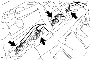 |
Disconnect the fuel injector connectors.
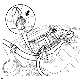 |
Disconnect the connector and 4 wire harness clamps shown in the illustration and disconnect the engine wire harness.
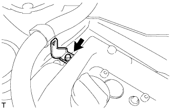 |
Remove the bolt and the wire harness bracket.
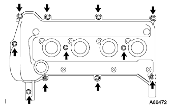 |
Remove the 9 bolts, 2 nuts and 2 seal washers and then remove the cylinder head cover sub-assembly.
| 42. REMOVE ENGINE MOUNTING INSULATOR SUB-ASSEMBLY RH |
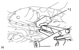 |
Place a wooden block on a jack underneath the oil pan sub-assembly.
| *1 | Wooden Block |
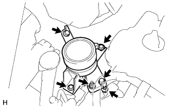 |
Remove the 4 bolts, the 2 nuts and the engine mounting insulator sub-assembly RH from the transverse engine engine mounting bracket and the vehicle.
| 43. REMOVE CRANKSHAFT DAMPER SUB-ASSEMBLY |
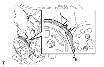 |
Set the No. 1 cylinder to TDC/compression.
Turn the crankshaft damper sub-assembly, and align its timing notch with timing mark "0" of the oil pump.
| *a | Timing Notch |
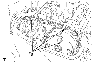 |
Check that the timing marks on the camshaft timing sprocket and the camshaft timing gear are all facing upward as shown in the illustration.
| *a | Timing Mark |
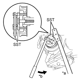 |
Using SST, loosen the bolt while holding the crankshaft damper sub-assembly.
| *a | Hold |
| *b | Turn |
Remove the SST and the bolt.
Remove the crankshaft damper sub-assembly from the crankshaft.
| 44. REMOVE CRANKSHAFT POSITION SENSOR |
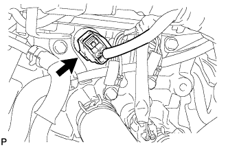 |
Disconnect the camshaft position sensor connector.
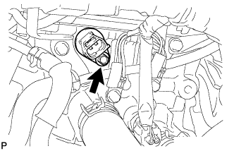 |
Remove the bolt and camshaft position sensor.
| 45. REMOVE CAMSHAFT TIMING OIL CONTROL VALVE ASSEMBLY |
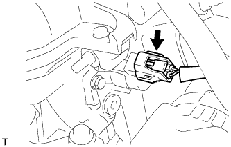 |
Disconnect the camshaft timing oil control valve assembly connector.
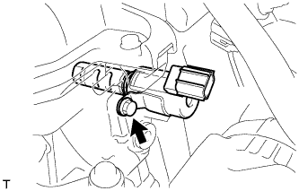 |
Remove the bolt and camshaft timing oil control valve assembly.
Remove the O-ring from the camshaft timing oil control valve assembly.
| 46. REMOVE WATER PUMP PULLEY |
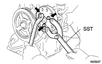 |
Using SST, hold the water pump pulley.
Remove the 3 bolts and the water pump pulley.
| 47. REMOVE ENGINE WATER PUMP ASSEMBLY |
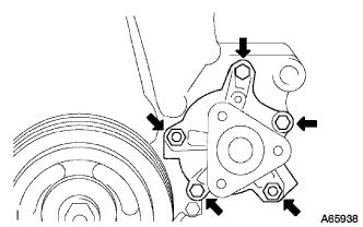 |
Remove the 3 bolts, 2 nuts the water pump assembly and water pump gasket.
| 48. REMOVE TRANSVERSE ENGINE ENGINE MOUNTING BRACKET |
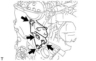 |
Remove the 4 bolts and the transverse engine engine mounting bracket.
| 49. REMOVE OIL PUMP ASSEMBLY |
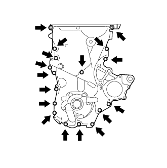 |
Remove the 16 bolts and the nut from the oil pump assembly.
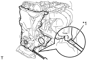 |
Using a screwdriver with its tip wrapped in protective tape, remove the oil pump assembly by prying between the cylinder head sub-assembly and cylinder block sub-assembly.
| *1 | Protective Tape |
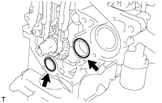 |
Remove the 2 O-rings from the cylinder block sub-assembly and the oil pan sub-assembly.
| 50. REMOVE OIL PUMP SEAL |
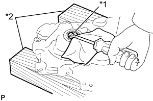 |
Using a screwdriver with its tip wrapped in protective tape and the wood block, remove the oil pump seal.
| *1 | Protective Tape |
| *2 | Wood block |
| 51. REMOVE NO. 1 CHAIN TENSIONER ASSEMBLY |
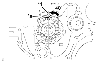 |
| *1 | Oil Jet |
| *a | Timing Mark (1 dot) |
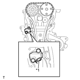 |
Pull up the stopper plate and hold it with its lock released.
| *1 | Stopper Plate |
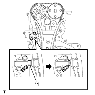 |
Unlock the plunger of the tensioner and push it in to the end.
| *1 | Plunger |
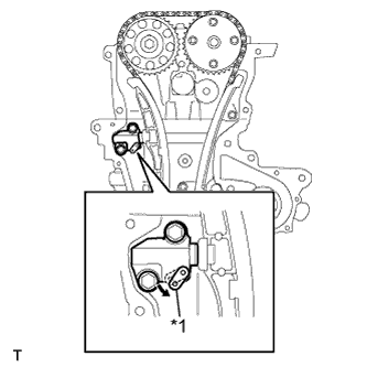 |
Pull down the stopper plate with the plunger pushed to the end and lock the plunger.
| *1 | Stopper Plate |
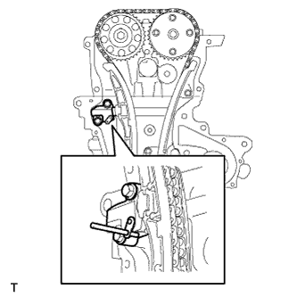 |
Insert a 3 mm (0.12 in.) diameter bar into the hole in the stopper plate and lock the plunger.
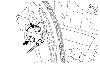 |
Remove the 2 bolts and the No. 1 chain tensioner.
| 52. REMOVE CHAIN TENSIONER SLIPPER |
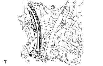 |
Remove the chain tensioner slipper.
| 53. REMOVE NO. 1 CHAIN VIBRATION DAMPER |
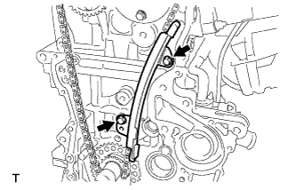 |
Remove the 2 bolts and the No. 1 chain vibration damper.
| 54. REMOVE CHAIN SUB-ASSEMBLY |
| 55. REMOVE CAMSHAFT |
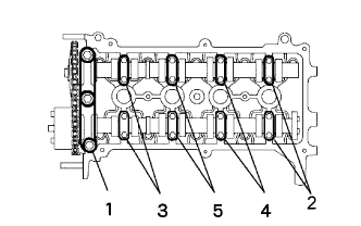 |
Using several steps, uniformly loosen and remove the 19 bearing cap bolts in the sequence shown in the illustration, and then remove No. 1 camshaft bearing cap and No. 2 camshaft bearing cap.
Remove the camshaft and No. 2 camshaft.
| 56. REMOVE CYLINDER HEAD SUB-ASSEMBLY |
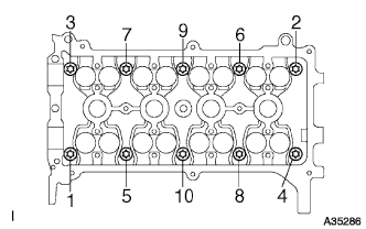 |
Using several steps, uniformly loosen and remove the 10 cylinder head bolts with an 8 mm bi-hexagon wrench in the sequence shown in the illustration. Remove the 10 plate washers.
| 57. REMOVE CYLINDER HEAD GASKET |
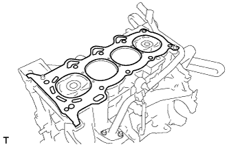 |
Remove the cylinder head gasket.