 |
Using a dial indicator, check the backlash near the center of the axle hub.
- Maximum:
- 0.05 mm (0.00197 in.)
REAR AXLE HUB (for Hatchback) > INSTALLATION |
| 1. INSTALL REAR AXLE HUB AND BEARING ASSEMBLY (for Rear Drum Brake) |
Install the axle hub and bearing onto the axle beam with the 4 bolts.
| 2. INSTALL REAR AXLE HUB AND BEARING ASSEMBLY (for Rear Disc Brake) |
Install the dust cover and the axle hub and bearing onto the axle beam with the 4 bolts.
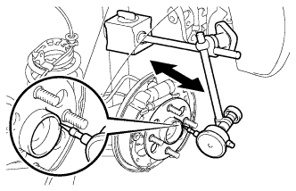
| 3. INSPECT REAR AXLE HUB BEARING BACKLASH (for Rear Drum Brake) |
|
Using a dial indicator, check the backlash near the center of the axle hub.
| 4. INSPECT REAR AXLE HUB BEARING BACKLASH (for Rear Disc Brake) |
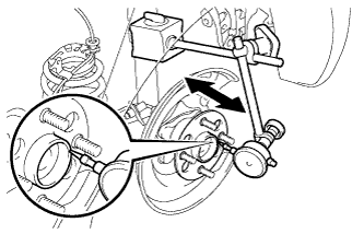 |
Using a dial indicator, check the backlash near the center of the axle hub.
| 5. INSPECT REAR AXLE HUB RUNOUT (for Rear Drum Brake) |
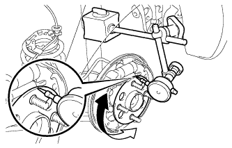 |
Using a dial indicator, check the runout of the surface of the axle hub.
| 6. INSPECT REAR AXLE HUB RUNOUT (for Rear Disc Brake) |
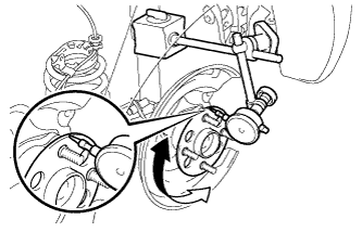 |
Using a dial indicator, check the runout of the surface of the axle hub.
| 7. CONNECT SKID CONTROL SENSOR WIRE (w/ ABS) |
Install the skid control sensor wire LH onto the rear axle beam assembly with the nut.
Connect the skid control sensor wire LH connector.
| 8. INSTALL REAR DISC (for Rear Disc Brake) |
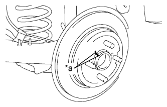 |
Align the matchmarks of the rear disc and axle hub and install the rear disc.
| *a | Matchmark |
| 9. INSTALL REAR DISC BRAKE CYLINDER MOUNTING (for Rear Disc Brake) |
Install the rear disc brake cylinder mounting to the axle beam with the 2 bolts.
| 10. INSTALL REAR DISC BRAKE PAD (for Rear Disc Brake) |
Install the 2 rear disc brake pads to the rear disc brake cylinder mounting.
| 11. INSTALL REAR DISC BRAKE CYLINDER ASSEMBLY (for Rear Disc Brake) |
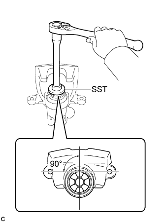 |
To compensate for pad wear when reusing the pad, use SST to push and turn the piston (LH side: counterclockwise, RH side: clockwise) to the position where the protrusion on the pad lines up properly with the piston groove.
Hold the rear disc brake pad guide pin, and install the rear disc brake cylinder assembly to the rear disc brake cylinder mounting with the 2 bolts.
| 12. INSTALL NO. 3 PARKING BRAKE CABLE ASSEMBLY (for Rear Disc Brake) |
Insert the parking brake cable into the disc brake cylinder and engage the clip claws of the parking brake cable to the rear disc brake cylinder guide.
Connect the cable end to the rear disc brake cylinder operation lever.
| 13. INSTALL REAR BRAKE DRUM SUB-ASSEMBLY (for Rear Drum Brake) |
| 14. INSTALL REAR WHEEL |
| 15. INSPECT AND ADJUST PARKING BRAKE LEVER TRAVEL (for Rear Disc Brake) |
| 16. INSPECT REAR WHEEL ALIGNMENT |
| 17. CHECK SPEED SENSOR SIGNAL (w/ ABS) |
| 18. CHECK SPEED SENSOR SIGNAL (w/ VSC) |