| NEXT | |
 |
CAN COMMUNICATION SYSTEM (for Hatchback) > HOW TO PROCEED WITH TROUBLESHOOTING |
| IMPORTANT POINTS CONCERNING TROUBLESHOOTING |
DTCs indicating a CAN communication malfunction are also stored due to internal or power source-related problems in ECUs or sensors of systems using CAN communication. Therefore, check whether codes indicating internal or power source-related problems in those systems are output together with the CAN communication DTCs.
It is possible to inspect the circuit of the DLC3 branch line or V bus main line for malfunctions by inspecting the terminals of the DLC3 using electrical tester.
It is possible to check which ECUs (sensors) are not able to communicate via CAN communication by checking the "Bus Check" function of the Techstream (when the DLC3 branch wire and V1 bus main wire are normal).
For past malfunctions of the V bus, the ECUs (sensors) which cannot communicate via CAN communication can be determined from the combination of CAN communication DTCs that are output.
The ECM detects malfunctions in the power train bus circuit and stores DTCs depending on the malfunctioning areas. The ECUs (sensors) which cannot communicate via CAN communication can be determined from the combination of CAN communication DTCs that are output.
When an open circuit malfunction is confirmed, before disconnecting the connectors for inspection, check whether the connectors are loose by pushing in the connector case.
When a connector is disconnected, check if the connector terminals or case is damaged, deformed, deteriorated, etc.
| 1.VEHICLE BROUGHT TO WORKSHOP |
| |||||
| 2.INSPECT BATTERY VOLTAGE |
| |||||
| 3.CHECK AND CLEAR DTC* |
Using the Techstream, perform the all DTCs check.
| |||||
| 4.CHECK INSTALLED SYSTEMS (ECU AND SENSOR) THAT USE CAN COMMUNICATION |
Based on the vehicle equipment and specifications, confirm the systems that use CAN communication (Click here).
| |||||
| 5.CHECK FOR OPEN CIRCUIT IN DLC3 BRANCH WIRE AND V BUS CIRCUIT MAIN WIRE AND SHORT CIRCUIT (CANH - CANL) |
Disconnect the cable from the negative (-) battery terminal before measuring the resistances of the main wire and branch wire.
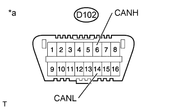 |
Measure the resistance of the DLC3.
| Tester Connection | Switch Condition | Specified Condition |
| D102-6 (CANH) - D102-14 (CANL) | Ignition switch off | 54 to 69 Ω |
| *a | Front view of DLC3 |
| Result | Proceed to |
| OK (54 to 69 Ω) | A |
| NG (Higher than 70 Ω) | B |
| NG (Below 54 Ω) | C |
|
| ||||
|
| ||||
| |||||
| 6.CHECK FOR SHORT TO +B IN CAN V BUS (CANH, CANL - BAT) |
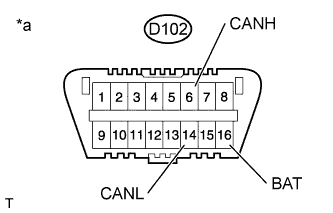 |
Measure the resistance of the DLC3.
| Tester Connection | Switch Condition | Specified Condition |
| D102-6 (CANH) - D102-16 (BAT) | Ignition switch off | 6 kΩ or higher |
| D102-14 (CANL) - D102-16 (BAT) | Ignition switch off | 6 kΩ or higher |
| *a | Front view of DLC3 |
|
| ||||
| |||||
| 7.CHECK FOR SHORT TO GND IN CAN V BUS (CANH, CANL - CG) |
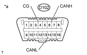 |
Measure the resistance of the DLC3.
| Tester Connection | Switch Condition | Specified Condition |
| D102-6 (CANH) - D102-4 (CG) | Ignition switch off | 200 Ω or higher |
| D102-14 (CANL) - D102-4 (CG) | Ignition switch off | 200 Ω or higher |
| *a | Front view of DLC3 |
|
| ||||
| |||||
| 8.CHECK ECUS CONNECTED TO CAN BUS* |
Connect the cable to the negative (-) battery terminal.
Select "Bus Check" from "System Select".
Check the display of the connected ECUs and sensors for a minute.
| Result | Proceed to |
| All ECUs and sensors connected to CAN communication system displayed on screen (CAN bus circuit currently normal) | A |
| A single ECU or sensor that should be connected to CAN communication is not displayed (ECU or sensor branch wire open or communication stop) | B |
| ECU or sensor that should be connected to CAN communication is not displayed or display is intermittent during check (ECU or sensor branch wire open on one side) | C |
|
| ||||
|
| ||||
| |||||
| 9.CHECK COMMUNICATION MALFUNCTION DTC (PAST DTC CHECK)* |
Select "Bus Check" from "System Select".
Write down all of the DTCs output from each ECU.
| |||||
| 10.CHECK DTC COMBINATION TABLE (V BUS BRANCH WIRE OPEN, PAST COMMUNICATION STOP MALFUNCTION) |
Based on the combination of output CAN communication system DTCs, determine which ECUs and sensors have a communication stop malfunction (Click here).
| |||||
| 11.PERFORM MALFUNCTION SIMULATION TEST (V BUS CIRCUIT MAIN WIRE PAST MALFUNCTION)* |
Using the Techstream, clear all DTCs.
Perform a malfunction simulation test on all harnesses and connectors related to the V1 bus main wire.
Check the DTCs that were output as a result of the malfunction simulation test. Then determine the malfunctioning area.
| |||||
| 12.ADJUST, REPAIR AND REPLACE |
| |||||
| 13.CLEAR DTC* |
Using the Techstream, clear all DTCs.
| |||||
| 14.CONFIRMATION TEST |
|
| ||||
|---|---|---|---|---|---|
