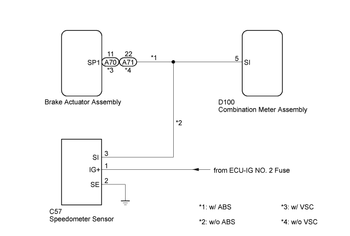
METER / GAUGE SYSTEM (for Hatchback) > Speedometer Malfunction |
| 1.SYSTEM CHECK |
Check the vehicle specifications.
| Result | Proceed to |
| w/ ABS | A |
| w/o ABS | B |
|
| ||||
| A | |
 |
| 2.READ VALUE USING TECHSTREAM (VEHICLE SPEED) |
Connect the Techstream to the DLC3.
Turn the ignition switch to ON.
Turn the Techstream on.
Enter the following menus: Chassis / ABS/VSC/TRC / Data List.
According to the display on the Techstream, read the Data List.
| Tester Display | Measurement Item/Range | Normal Condition | Diagnostic Note |
| Vehicle Speed | Maximum wheel speed sensor reading Min.: 0 km/h Max.: 326 km/h | Actual vehicle speed | Speed indicated on speedometer |
| Result | Proceed to |
| OK | A |
| NG (for Hatchback with VSC) | B |
| NG (for Hatchback without VSC) | C |
|
| ||||
|
| ||||
| A | |
|
| 3.INSPECT COMBINATION METER ASSEMBLY (OUTPUT VOLTAGE) |
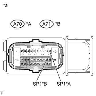 |
Disconnect the A70*1 or A71*2 brake actuator assembly connector.
Measure the voltage according to the value(s) in the table below.
| Tester Connection | Switch Condition | Specified Condition |
| A70-11 (SP1)*1 - Body ground A71-22 (SP1)*2 - Body ground | Ignition switch ON | 11 to 14 V |
| *A | w/ VSC |
| *B | w/o VSC |
| *a | Front view of wire harness connector (to brake actuator assembly) |
Reconnect the A70*1 or A71*2 brake actuator assembly connector.
|
| ||||
| OK | |
|
| 4.INSPECT COMBINATION METER ASSEMBLY (INPUT WAVEFORM) |
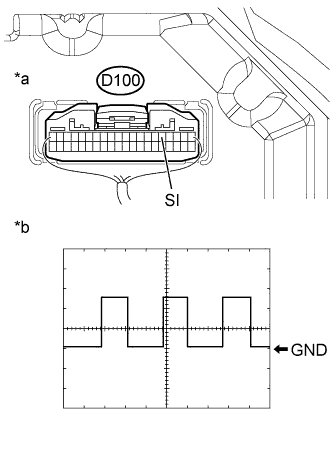 |
Check the input waveform.
Remove the combination meter assembly with the connector(s) still connected.
Connect an oscilloscope to terminal D100-5 (SI) and body ground.
Turn the ignition switch to ON.
Turn the wheel slowly.
Check the signal waveform according to the condition(s) in the table below.
| Item | Condition |
| Tool setting | 5 V/DIV., 20 ms./DIV. |
| Condition | Driving at approx. 20 km/h |
| *a | Component with harness connected (Combination Meter Assembly) |
| *b | Waveform |
|
| ||||
| OK | ||
 | ||
| ||
| 5.CHECK HARNESS AND CONNECTOR (BRAKE ACTUATOR ASSEMBLY - COMBINATION METER ASSEMBLY) |
Disconnect the D100 combination meter assembly connector.
Disconnect the A70*1 or A71*2 brake actuator assembly connector.
Measure the resistance according to the value(s) in the table below.
| Tester Connection | Condition | Specified Condition |
| D100-5 (SI) - A70-11 (SP1)*1 D100-5 (SI) - A71-22 (SP1)*2 | Always | Below 1 Ω |
| D100-5 (SI) - Body ground | Always | 10 kΩ or higher |
|
| ||||
| OK | ||
| ||
| ||
| 6.PERFORM ACTIVE TEST USING TECHSTREAM (SPEED METER OPERATION) |
Connect the Techstream to the DLC3.
Turn the ignition switch to ON.
Turn the Techstream on.
Enter the following menus: Body Electrical / Combination Meter / Active Test.
According to the display on the Techstream, perform the Active Test.
| Tester Display | Test Part | Control Range | Diagnostic Note |
| Speed Meter Operation | Speedometer | 0, 40, 80, 120, 160, 200, 240 (km/h, mph) | Vehicle is stopped and engine is idling |
| Acceptable range (km/h or mph): [Control range → Speedometer display] for mph
|
|
| ||||
| OK | |
|
| 7.INSPECT SPEEDOMETER SENSOR |
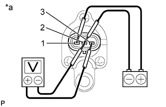 |
Remove the speedometer sensor.
Connect the positive (+) lead from the battery to terminal 1 and the negative(-) lead to terminal 2.
Connect the positive (+) lead from the tester to terminal 3 and the negative (-) lead to terminal 2.
Rotate the shaft.
Check that the voltage output between terminals 2 and 3 varies between 0 V and 11 V.
| *a | Component without harness connected (Speedometer Sensor) |
Reinstall the speedometer sensor.
|
| ||||
| OK | |
|
| 8.CHECK HARNESS AND CONNECTOR (SPEEDOMETER SENSOR - COMBINATION METER ASSEMBLY) |
Disconnect the D100 combination meter assembly connector.
Disconnect the C57 speedometer sensor connector.
Measure the resistance according to the value(s) in the table below.
| Tester Connection | Condition | Specified Condition |
| D100-5 (SI) - C57-3 (SI) | Always | Below 1 Ω |
| C57-2 (SE) - Body ground | Always | 10 kΩ or higher |
Reconnect the D100 combination meter assembly connector.
Measure the voltage according to the value(s) in the table below.
| Tester Connection | Switch Condition | Specified Condition |
| C57-1 (IG+) - Body ground | Ignition switch ON | 11 to 14 V |
Reconnect the C57 speedometer sensor connector.
|
| ||||
| OK | ||
| ||
| ||

