AUDIO / VIDEO RADIO ANTENNA CORD INSTALLATION
PROCEDURE

 86101J
1.INSTALL NO. 2 ANTENNA CORD SUB-ASSEMBLY
Align the positioning tape of the No. 2 antenna cord sub-assembly with the protrusion of the roof headlining assembly and wrap a new adhesive tape around them as shown in the part of the illustration labeled A.
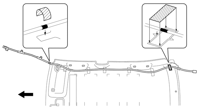
| *a | Marking | - | - |

|
Adhesive Tape | 
|
Positioning Tape |

|
Front | - | - |
Align the No. 2 antenna cord sub-assembly positioning tape with the marking of the roof headlining assembly.
Install the No. 2 antenna cord sub-assembly onto the roof headlining assembly with a new adhesive tape.
Align the No. 2 antenna cord sub-assembly with the markings of the roof headlining assembly.
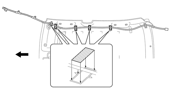
| *a | Marking | - | - |
|
|
Adhesive Tape |
|
Front |
Install the No. 2 antenna cord sub-assembly onto the roof headlining assembly with 5 new adhesive tapes.
Install the rest of the No. 2 antenna cord sub-assembly onto the roof headlining assembly with a new adhesive tape.
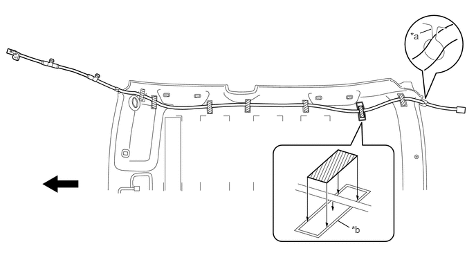
| *a | Cutout | *b | Marking |
|
|
Adhesive Tape |
|
Front |
Insert the No. 2 antenna cord sub-assembly into the cutout of the roof headlining assembly.
63310
2.INSTALL ROOF HEADLINING ASSEMBLY
86101
3.INSTALL ANTENNA CORD SUB-ASSEMBLY (for LHD)
Engage the 4 clamps and 3 guides and install the antenna cord sub-assembly.
86101
4.INSTALL ANTENNA CORD SUB-ASSEMBLY (for RHD)
Engage the 3 clamps and 3 guides, and install the antenna cord sub-assembly.
55085
5.INSTALL NO. 2 HEATER TO REGISTER DUCT SUB-ASSEMBLY (for LHD)
55084E
6.INSTALL NO. 1 HEATER TO REGISTER DUCT SUB-ASSEMBLY (for RHD)
55950G
7.INSTALL DEFROSTER NOZZLE ASSEMBLY
Engage the 3 guides and install the defroster nozzle assembly.
Install the 3 screws.
Connect the connector.
55301
8.INSTALL INSTRUMENT PANEL SUB-ASSEMBLY