STEERING COLUMN STEERING COLUMN ASSEMBLY INSTALLATION
CAUTION / NOTICE / HINT
- CAUTION:
-
Some of these service operations affect the SRS airbag system. Read the precautionary notices concerning the SRS airbag system before servicing.
-
Click hereVehicle Interior>SUPPLEMENTAL RESTRAINT SYSTEMS>AIRBAG SYSTEM>PRECAUTION
PROCEDURE

 45879A
1.INSTALL BREAK AWAY CAPSULE
Install 2 new break away capsules to the steering column assembly.
89650
2.INSTALL POWER STEERING ECU ASSEMBLY
3.INSTALL STEERING COLUMN ASSEMBLY
Install the steering column assembly to the instrument panel reinforcement assembly with the bolt and 2 nuts.
- Torque:
- 25 N*m (255 kgf*cm, 18 ft.*lbf)
Connect all the connectors and engage all the wire harness clamps to the steering column assembly.
55106
4.INSTALL BRAKE PEDAL SUPPORT SUB-ASSEMBLY (for LHD)
55106
5.INSTALL BRAKE PEDAL SUPPORT SUB-ASSEMBLY (for RHD)
45209
6.INSTALL STEERING SLIDING YOKE SUB-ASSEMBLY
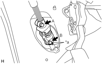
| *a | Matchmark |
Align the matchmarks on the steering sliding yoke sub-assembly and steering link assembly.
Install the steering sliding yoke sub-assembly to the steering link assembly.
Install bolt B.
- Torque:
- 35.3 N*m (360 kgf*cm, 26 ft.*lbf)
Tighten bolt A.
- Torque:
- 35.3 N*m (360 kgf*cm, 26 ft.*lbf)
45259A
7.INSTALL COLUMN HOLE COVER SILENCER SHEET
Install the column hole cover silencer sheet with the 2 clips.
55432B
8.INSTALL LOWER INSTRUMENT PANEL FINISH PANEL (for LHD)
55432B
9.INSTALL LOWER INSTRUMENT PANEL FINISH PANEL (for RHD)
55606
10.INSTALL NO. 1 INSTRUMENT PANEL UNDER COVER SUB-ASSEMBLY
11.INSTALL COMBINATION SWITCH ASSEMBLY WITH SPIRAL CABLE
Using pliers, pinch the clamp and attach the claw to install the combination switch assembly with spiral cable to the steering column assembly.
Connect all the connectors to the combination switch assembly with spiral cable.
45286B
12.INSTALL UPPER STEERING COLUMN COVER
Engage the claw and install the upper steering column cover.
45287
13.INSTALL LOWER STEERING COLUMN COVER
Engage the 3 claws to install the lower steering column cover.
Install the 3 screws.
45289A
14.INSTALL STEERING COLUMN COVER SUPPORT (w/ Smart Entry and Start System)
Engage the 4 claws and install the steering column cover support.
15.PLACE FRONT WHEELS FACING STRAIGHT AHEAD
84306
16.ADJUST SPIRAL CABLE SUB-ASSEMBLY
45100
17.INSTALL STEERING WHEEL ASSEMBLY
45130
18.INSTALL HORN BUTTON ASSEMBLY (w/ Airbag System)
45130
19.INSTALL HORN BUTTON ASSEMBLY (w/o Airbag System)
45186
20.INSTALL NO. 2 STEERING WHEEL LOWER COVER
21.CONNECT CABLE TO NEGATIVE BATTERY TERMINAL
- Torque:
- 5.4 N*m (55 kgf*cm, 48 in.*lbf)
22.INSPECT SRS WARNING LIGHT
23. PERFORM CALIBRATION OF TORQUE SENSOR ZERO POINT