THEFT DETERRENT / KEYLESS ENTRY THEFT DETERRENT SYSTEM Theft Deterrent System is not Unset when Engine is Running
DESCRIPTION
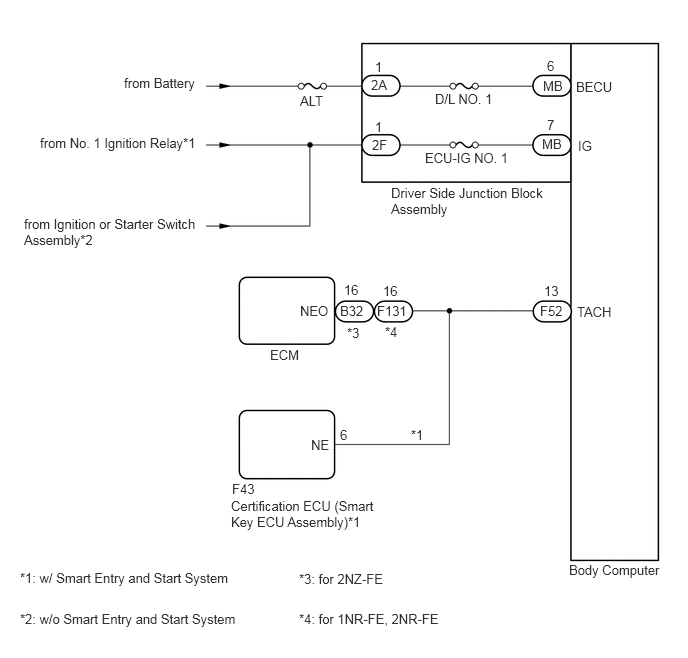
The theft deterrent system is unset when the IG signal and engine speed signal are input to the body computer for 2 seconds or more continuously.
The engine speed signal is sent from the ECM to the body computer*1 or certification ECU (smart key ECU assembly)*2. For this reason, if there is an abnormality in an ECU or wire harness, the system may not function correctly.
*1: w/o Smart Entry and Start System
*2: w/ Smart Entry and Start System
WIRING DIAGRAM
CAUTION / NOTICE / HINT
- NOTICE:
- ·
Before replacing the certification ECU (smart key ECU assembly) or ECM, refer to Service Bulletin.*1
*1: w/ Smart Entry and Start System
·Inspect the fuses for circuits related to this system before performing the following procedure.
PROCEDURE
Disconnect the driver side junction block assembly connectors.
Measure the voltage according to the value(s) in the table below.

| *a | Front view of wire harness connector
(to Driver Side Junction Block Assembly) |
- | - |
- Standard Voltage:
Tester Connection Switch Condition Specified Condition 2A-1 - Body ground Always 11 to 14 V 2F-1 - Body ground Ignition switch ON 11 to 14 V 2F-1 - Body ground Ignition switch off Below 1 V
- Result:
Proceed to OK NG
OK
NG
Remove the body computer.
Click herePower Source / Network>POWER DISTRIBUTION>MAIN BODY ECU>REMOVAL
Disconnect the driver side junction block assembly connectors.
Measure the resistance according the value(s) in the table below.
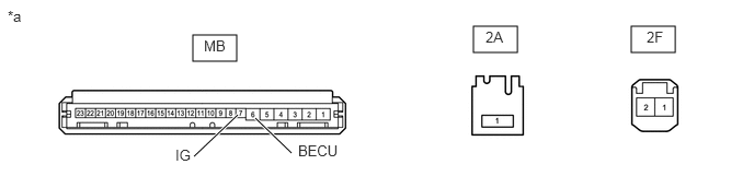
| *a | Component without harness connected
(Driver Side Junction Block Assembly) |
- | - |
- Standard Resistance:
Tester Connection Condition Specified Condition 2A-1 - MB-6 (BECU) Always Below 1 Ω 2F-1 - MB-7 (IG) Always Below 1 Ω
- Result:
Proceed to OK NG
OK
NG
Install the body computer to the driver side junction block assembly.
Click herePower Source / Network>POWER DISTRIBUTION>MAIN BODY ECU>INSTALLATION
Reconnect the body computer connector.
Reconnect the 2A and 2F driver side junction block assembly connectors.
Remove the driver side junction block assembly with connectors still connected.
Click herePower Source / Network>POWER DISTRIBUTION>MAIN BODY ECU>REMOVAL
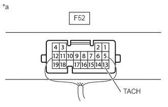
| *a | Component with harness connected
(Body Computer) |
Check the engine speed input signal waveform at the terminal of body computer.
- Standard Frequency:
Tester Connection Condition Specified Condition F52-13 (TACH) - Body ground Engine stopped Not pulse generation F52-13 (TACH) - Body ground Engine running Pulse generation
- Result:
Result Proceed to NG (w/ Smart Entry and Start System) A NG (w/o Smart Entry and Start System) B OK C
A
B
C
for 2NZ-FE
Disconnect the F52 body computer connector.
Disconnect the B32 ECM connector.
Disconnect the F43 certification ECU (smart key ECU assembly) connector.
Measure the resistance according to the value(s) in the table below.
- Standard Resistance:
Tester Connection Condition Specified Condition F52-13 (TACH) - B32-16 (NEO) Always Below 1 Ω F52-13 (TACH) - F43-6 (NE) Always Below 1 Ω B32-16 (NEO) - F43-6 (NE) Always Below 1 Ω F52-13 (TACH) or B32-16 (NEO) - Body ground Always 10 kΩ or higher F52-13 (TACH) or F43-6 (NE) - Body ground Always 10 kΩ or higher B32-16 (NEO) or F43-6 (NE) - Body ground Always 10 kΩ or higher
for 1NR-FE
Disconnect the F52 body computer connector.
Disconnect the F131 ECM connector.
Disconnect the F43 certification ECU (smart key ECU assembly) connector.
Measure the resistance according to the value(s) in the table below.
- Standard Resistance:
Tester Connection Condition Specified Condition F52-13 (TACH) - F131-16 (NEO) Always Below 1 Ω F52-13 (TACH) - F43-6 (NE) Always Below 1 Ω F131-16 (NEO) - F43-6 (NE) Always Below 1 Ω F52-13 (TACH) or F131-16 (NEO) - Body ground Always 10 kΩ or higher F52-13 (TACH) or F43-6 (NE) - Body ground Always 10 kΩ or higher F131-16 (NEO) or F43-6 (NE) - Body ground Always 10 kΩ or higher
- Result:
Proceed to OK NG
OK
NG
for 2NZ-FE
Disconnect the F52 body computer connector.
Reconnect the B32 ECM connector.
Reconnect the F43 certification ECU (smart key ECU assembly) connector.
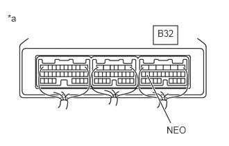
| *a | Component with harness connected
(ECM) |
Check the engine speed input signal waveform at the terminal of ECM.
- Standard Frequency:
Tester Connection Condition Specified Condition B32-16 (NEO) - Body ground Engine stopped Not pulse generation B32-16 (NEO) - Body ground Engine running Pulse generation
for 1NR-FE
Disconnect the F52 body computer connector.
Reconnect the F131 ECM connector.
Reconnect the F43 certification ECU (smart key ECU assembly) connector.
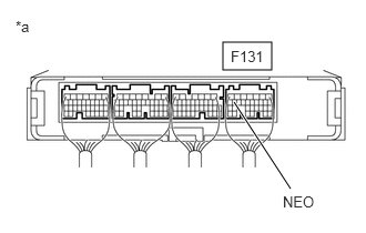
| *a | Component with harness connected
(ECM) |
Check the engine speed input signal waveform at the terminal of ECM.
- Standard Frequency:
Tester Connection Condition Specified Condition F131-16 (NEO) - Body ground Engine stopped Not pulse generation F131-16 (NEO) - Body ground Engine running Pulse generation
- Result:
Result Proceed to NG A OK B
A
B
for 2NZ-FE
Disconnect the F52 body computer connector.
Disconnect the B32 ECM connector.
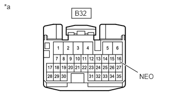
| *a | Front view of wire harness connector
(to ECM) |
Measure the voltage according to the value(s) in the table below.
- Standard Voltage:
Tester Connection Condition Specified Condition B32-16 (NEO) - Body ground Engine stopped 11 to 14 V
for 1NR-FE
Disconnect the F52 body computer connector.
Disconnect the F131 ECM connector.
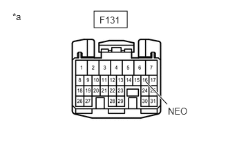
| *a | Front view of wire harness connector
(to ECM) |
Measure the voltage according to the value(s) in the table below.
- Standard Voltage:
Tester Connection Condition Specified Condition F131-16 (NEO) - Body ground Engine stopped 11 to 14 V
- Result:
Result Proceed to NG A OK (for 2NZ-FE) B OK (for 1NR-FE) C
A
B
C
Replace the certification ECU (smart key ECU assembly) with a new one.
- HINT:
-
Refer to Service Bulletin.
- Result:
Proceed to NEXT
NEXT
for 2NZ-FE
Disconnect the F52 body computer connector.
Reconnect the B32 ECM connector.
Reconnect the F43 certification ECU (smart key ECU assembly) connector.
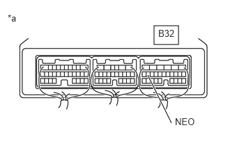
| *a | Component with harness connected
(ECM) |
Check the engine speed input signal waveform at the terminal of ECM.
- Standard Frequency:
Tester Connection Condition Specified Condition B32-16 (NEO) - Body ground Engine stopped Not pulse generation B32-16 (NEO) - Body ground Engine running Pulse generation
for 1NR-FE
Disconnect the F52 body computer connector.
Reconnect the F131 ECM connector.
Reconnect the F43 certification ECU (smart key ECU assembly) connector.
| *a | Component with harness connected
(ECM) |
Check the engine speed input signal waveform at the terminal of ECM.
- Standard Frequency:
Tester Connection Condition Specified Condition F131-16 (NEO) - Body ground Engine stopped Not pulse generation F131-16 (NEO) - Body ground Engine running Pulse generation
- Result:
Result Proceed to OK A NG (for 2NZ-FE) B NG (for 1NR-FE) C
A
B
C
for 2NR-FE
Disconnect the F52 body computer connector.
Disconnect the F131 ECM connector.
Measure the resistance according to the value(s) in the table below.
- Standard Resistance:
Tester Connection Condition Specified Condition F52-13 (TACH) - F131-16 (NEO) Always Below 1 Ω F52-13 (TACH) or F131-16 (NEO) - Body ground Always 10 kΩ or higher
- Result:
Result Proceed to OK (for 2NR-FE) A NG B
A
B