K312 CVT CONTINUOUSLY VARIABLE TRANSAXLE ASSEMBLY REMOVAL
PROCEDURE

 1. PRECAUTION
- NOTICE:
-
After turning the ignition switch off, waiting time may be required before disconnecting the cable from the negative (-) battery terminal. Therefore, make sure to read the disconnecting the cable from the negative (-) battery terminal notices before proceeding with work.
-
Click hereGeneral>INTRODUCTION>REPAIR INSTRUCTION>PRECAUTION
2.DISCONNECT CABLE FROM NEGATIVE BATTERY TERMINAL
- NOTICE:
-
When disconnecting the cable, some systems need to be initialized after the cable is reconnected.
-
Click hereGeneral>INTRODUCTION>REPAIR INSTRUCTION>INITIALIZATION
3.ALIGN FRONT WHEELS FACING STRAIGHT AHEAD
4.REMOVE FRONT WHEELS
51442C
5.REMOVE ENGINE UNDER COVER LH (w/o Metal Type Under Cover)
51441C
6.REMOVE ENGINE UNDER COVER RH (w/o Metal Type Under Cover)
51451A
7.REMOVE CENTER ENGINE UNDER COVER (w/ Metal Type Under Cover)
51405A
8.REMOVE NO. 1 ENGINE UNDER COVER SUB-ASSEMBLY (w/ Metal Type Under Cover)
9.DRAIN ENGINE COOLANT
10.DRAIN CONTINUOUSLY VARIABLE TRANSAXLE FLUID
Click hereDrivetrain>K312 CVT>OIL PAN>REMOVAL
17880
11.REMOVE AIR CLEANER HOSE ASSEMBLY
12.REMOVE AIR CLEANER CAP SUB-ASSEMBLY
17801
13.REMOVE AIR CLEANER FILTER ELEMENT SUB-ASSEMBLY
17701
14.REMOVE AIR CLEANER CASE SUB-ASSEMBLY
28800
15.REMOVE BATTERY
74431
16.REMOVE BATTERY TRAY
74410
17.REMOVE BATTERY CARRIER ASSEMBLY
58910C
18.REMOVE REAR CONSOLE BOX ASSEMBLY (w/ Console Box Lid)
58910C
19.REMOVE REAR CONSOLE BOX ASSEMBLY (w/o Console Box Lid)
33820B
20.DISCONNECT TRANSMISSION CONTROL CABLE ASSEMBLY
82121
21.DISCONNECT ENGINE WIRE
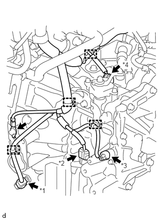
| *1 | Heated Oxygen Sensor Connector |
| *2 | Transmission Wire Connector |
| *3 | Transmission Revolution Sensor (NIN) Connector |
| *4 | Park/Neutral Position Switch Assembly Connector |
Disconnect the heated oxygen sensor connector.
Disconnect the transmission wire connector.
Disconnect the transmission revolution sensor (NIN) connector.
Disconnect the park/neutral position switch assembly connector.
Remove the bolt to disconnect the engine wire from the continuously variable transaxle assembly.
Disengage the 4 clamps to disconnect the engine wire from the continuously variable transaxle assembly.
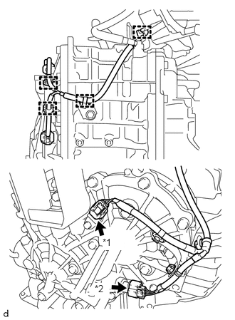
| *1 | Transmission Revolution Sensor (NOUT) Connector |
| *2 | Oil Pressure Sensor Connector |
Disconnect the transmission revolution sensor (NOUT) connector.
Disconnect the oil pressure sensor connector.
Disengage the 4 clamps to disconnect the engine wire from the continuously variable transaxle assembly.
16260
22.DISCONNECT WATER BY-PASS HOSE ASSEMBLY
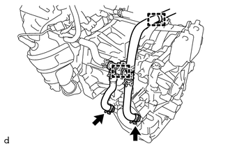
Slide the 2 hose clips and disconnect the 2 water by-pass hoses from the transmission oil cooler.
Disengage the 2 clamps to separate the water by-pass hose assembly from the continuously variable transaxle assembly.
33823
23.REMOVE NO. 1 TRANSMISSION CONTROL CABLE BRACKET
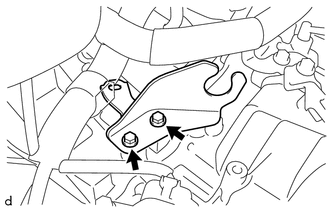
Remove the 2 bolts and No. 1 transmission control cable bracket from the continuously variable transaxle assembly.
24.SECURE STEERING WHEEL
45259A
25.REMOVE COLUMN HOLE COVER SILENCER SHEET
45209
26.DISCONNECT STEERING SLIDING YOKE SUB-ASSEMBLY
45025D
27.SEPARATE NO. 1 STEERING COLUMN HOLE COVER SUB-ASSEMBLY
57533B
28.REMOVE FRONT FLOOR CENTER BRACE (for Sedan)
57533B
29.REMOVE FRONT FLOOR CENTER BRACE (for Hatchback)
17410
30.REMOVE FRONT EXHAUST PIPE ASSEMBLY (for Sedan)
17410
31.REMOVE FRONT EXHAUST PIPE ASSEMBLY (for Hatchback)
43498A
32.REMOVE NO. 1 DRIVE SHAFT HEAT INSULATOR
33.REMOVE FRONT DRIVE SHAFT ASSEMBLIES
34.SUPPORT ENGINE ASSEMBLY
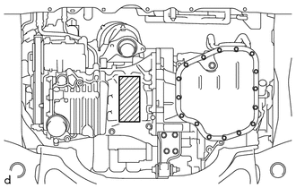

|
Attachment Placement Position |
Place height adjustment attachments or plate lift attachments in the position shown in the illustration and set an engine lifter underneath the engine assembly.
- NOTICE:
-
Using height adjustment attachments and plate lift attachments, keep the engine assembly horizontal.
51201
35.REMOVE FRONT SUSPENSION CROSSMEMBER SUB-ASSEMBLY
12364A
36.REMOVE ENGINE LATERAL CONTROL ROD
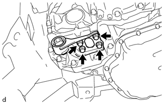
Remove the 4 bolts and engine lateral control rod from the continuously variable transaxle assembly.
30400
37.SUPPORT CONTINUOUSLY VARIABLE TRANSAXLE ASSEMBLY
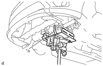
| *a | Lashing Belt |
Using a transmission jack, support the continuously variable transaxle assembly.
- NOTICE:
- ·
Adjust the attachment of the transmission jack to securely fix the continuously variable transaxle assembly to the transmission jack.
·To prevent the transaxle oil (CVT) pan sub-assembly from deforming, do not place any attachments under the transaxle oil (CVT) pan sub-assembly of the continuously variable transaxle assembly.
·Using a lashing belt or a rope, fix the continuously variable transaxle assembly to the transmission jack.
28100
38.REMOVE STARTER ASSEMBLY
11363A
39.REMOVE FLYWHEEL HOUSING SIDE COVER
32101G
40.REMOVE DRIVE PLATE AND TORQUE CONVERTER ASSEMBLY SETTING BOLT
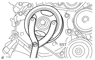
Using SST, hold the crankshaft pulley.
- SST
- 09960-10010 (09962-01000, 09963-01000)
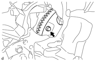
Remove the 6 drive plate and torque converter assembly setting bolts.
12372A
41.REMOVE ENGINE MOUNTING INSULATOR LH
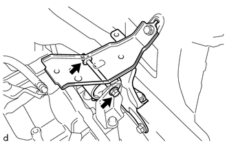
Remove the bolt and nut to separate the engine mounting insulator LH from the engine mounting bracket LH.
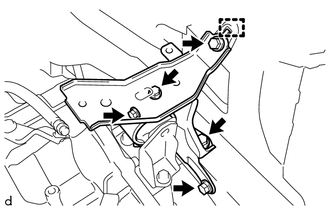
Remove the 5 bolts.
Disengage the hook to remove the engine mounting insulator LH from the vehicle body.
12325A
42.REMOVE ENGINE MOUNTING BRACKET LH
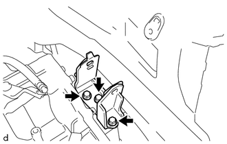
Remove the 3 bolts and engine mounting bracket LH from the continuously variable transaxle assembly.
30400
43.REMOVE CONTINUOUSLY VARIABLE TRANSAXLE ASSEMBLY
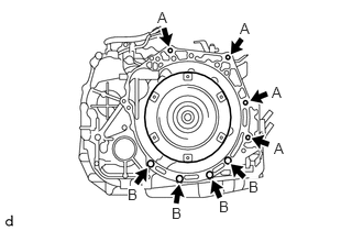
Remove the 8 bolts and continuously variable transaxle assembly from the engine assembly.
- NOTICE:
-
To prevent damage to the knock pins, do not pry between the continuously variable transaxle assembly and engine assembly.
- HINT:
- ·
Bolt (A): Remove from continuously variable transaxle assembly side.
·Bolt (B): Remove from engine assembly side.
32000A
44.REMOVE TORQUE CONVERTER ASSEMBLY
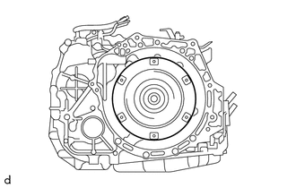
Remove the torque converter assembly from the continuously variable transaxle assembly.
- NOTICE:
-
Remove the torque converter assembly from the input shaft horizontally.
30400E
45.REMOVE CVT OIL PUMP TYPE T OIL SEAL
- NOTICE:
- ·
Do not remove the front oil pump assembly from the CVT main body, as there is a possibility of the entry of dust and foreign matter.
·Clean the work area, the tools to be used, and other equipment, etc. thoroughly before the operation, as there is the possibility that a CVT malfunction, which could prevent the vehicle from being able to be driven, could occur if dust or fine foreign matter enters the CVT.
·Do not use cotton work gloves, cloths, or paper towels, etc. that may produce lint, dust or foreign matter.
·Perform the operation as quickly as possible, as dust and foreign matter could enter the CVT while the torque converter assembly is removed.
·Do not use an air gun until the torque converter assembly has been installed, as it could cause dust and foreign matter to be stirred up.
Clean the tips of both the claws of SST and the center bolt.
- SST
- 09308-10010
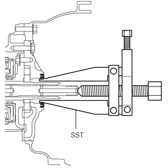
Using SST, remove the CVT oil pump type T oil seal.
- NOTICE:
-
Pay attention to the angle of the claws when opening them, and ensure that they do not come into contact with the oil pump housing, as there is the possibility that metal particles could be produced if they do.
46.REMOVE WIRE HARNESS CLAMP BRACKET
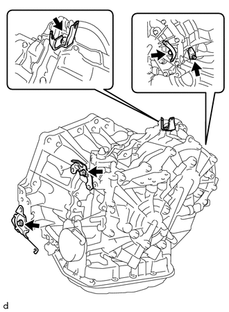
Remove the 5 bolts and 5 wire harness clamp brackets from the continuously variable transaxle assembly.
35123B
47.REMOVE TRANSMISSION BREATHER SKIRT
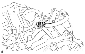
Separate the No. 1 breather plug (CVT) from the clamp.
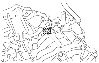
Remove the clamp from the transmission breather skirt.
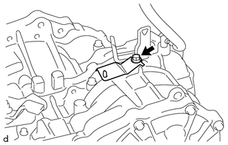
Remove the bolt and transmission breather skirt from the continuously variable transaxle assembly.
48.REMOVE STRAIGHT SCREW PLUG
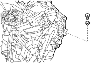
Remove the straight screw plug and gasket from the continuously variable transaxle assembly.
35141D
49.REMOVE BREATHER PLUG HOSE
- HINT:
-
Perform this procedure only when replacement of the breather plug hose is necessary.
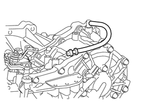
Remove the breather plug hose from the continuously variable transaxle assembly.
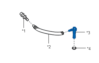
| *1 | No. 1 Breather Plug (CVT) |
| *2 | Breather Plug Hose |
| *3 | No. 2 Breather Plug (CVT) |
| *4 | O-ring |
Remove the No. 1 breather plug (CVT) and No. 2 breather plug (CVT) from the breather plug hose.
Remove the O-ring from the No. 2 breather plug (CVT).
32000A
50.INSPECT TORQUE CONVERTER ASSEMBLY
32101
51.INSPECT DRIVE PLATE AND RING GEAR SUB-ASSEMBLY