C54 MANUAL TRANSMISSION / TRANSAXLE MANUAL TRANSAXLE ASSEMBLY(for 1NR-FE) INSTALLATION
PROCEDURE

 33403K
1.INSTALL SPEEDOMETER DRIVEN HOLE COVER SUB-ASSEMBLY
Apply a light coat of gear oil to a new O-ring and install it to the speedometer driven hole cover sub-assembly.
- NOTICE:
-
Do not twist the O-ring.
Install the speedometer driven hole cover sub-assembly to the manual transaxle assembly with the bolt.
- Torque:
- 11.3 N*m (115 kgf*cm, 8 ft.*lbf)
- NOTICE:
-
Make sure that the O-ring is not damaged or does not jump out of position during installation.
2.INSTALL WIRE HARNESS CLAMP BRACKET
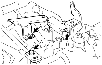
Install the 3 wire harness clamp brackets to the manual transaxle assembly with the 3 bolts.
- Torque:
- Bolt A : 12.8 N*m (131 kgf*cm, 9 ft.*lbf)
- Bolt B : 25.5 N*m (260 kgf*cm, 19 ft.*lbf)
30300
3.INSTALL MANUAL TRANSAXLE ASSEMBLY
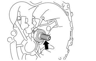

|
Clutch Spline Grease |
Apply clutch spline grease to the input shaft spline.
- Grease:
Toyota Genuine Clutch Spline Grease or equivalent
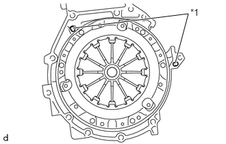
| *1 | Knock Pin |
Confirm that the 2 knock pins are installed on the engine assembly and are not damaged.
Align the input shaft with the clutch disc assembly and install the manual transaxle assembly to the engine assembly.
- NOTICE:
- ·
Make sure that the wire harness or similar items are not pinched between the contact surfaces.
·Do not forcibly pry on the manual transaxle assembly.
·When mounting the manual transaxle assembly to the engine assembly, make sure to securely fit the knock pins into the knock holes.
·When tightening the bolts, be sure that the contact surfaces of the engine assembly and manual transaxle assembly are in close contact with one another.
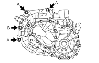
Install the 4 bolts from the manual transaxle assembly side.
- Torque:
- 64 N*m (653 kgf*cm, 47 ft.*lbf)
- Bolt Length:
Item Length Bolt A 45 mm (1.77 in.) Bolt B 80 mm (3.15 in.)
| *a | Adhesive |
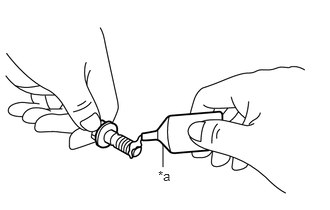
Clean and degrease the engine mounting bracket LH installation bolts and bolt holes.
Apply adhesive to 2 or 3 threads on the ends of the 5 bolts.
- Adhesive:
Toyota Genuine Adhesive 1324, Three Bond 1324 or equivalent
- NOTICE:
-
To prevent contamination by foreign matter, install immediately after applying adhesive.
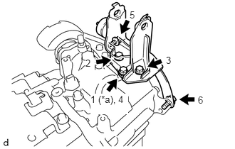
| *a | Temporarily Tighten |
Install the engine mounting bracket LH to the manual transaxle assembly with the 5 bolts in the order shown in the illustration.
- Torque:
- 64 N*m (653 kgf*cm, 47 ft.*lbf)
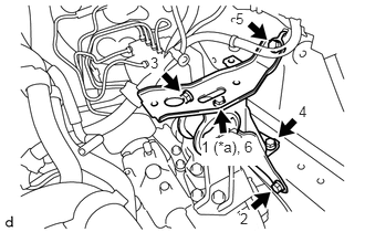
| *a | Temporarily Tighten |
Engage the hook to temporarily install the engine mounting insulator LH to the body.
Install the 5 bolts in the order shown in the illustration.
- Torque:
- 52 N*m (530 kgf*cm, 38 ft.*lbf)
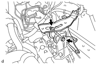
Install the engine mounting insulator LH to the engine mounting bracket LH with the bolt and nut.
- Torque:
- 52 N*m (530 kgf*cm, 38 ft.*lbf)
- HINT:
-
Turn the bolt while holding the nut.
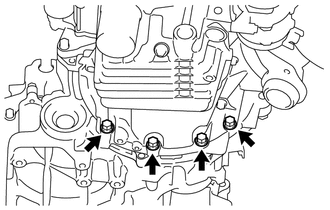
Install the 4 bolts from the engine assembly side.
- Torque:
- 39 N*m (398 kgf*cm, 29 ft.*lbf)
12313
4.INSTALL ENGINE MOVING CONTROL ROD BRACKET
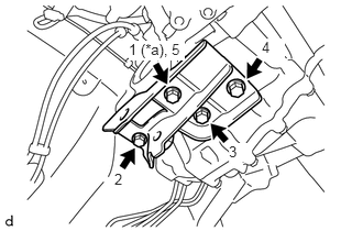
| *a | Temporarily Tighten |
Install the engine moving control rod bracket to the manual transaxle assembly with the 4 bolts in the order shown in the illustration.
- Torque:
- 45 N*m (459 kgf*cm, 33 ft.*lbf)
51201
5.INSTALL FRONT SUSPENSION CROSSMEMBER SUB-ASSEMBLY
28100
6.INSTALL STARTER ASSEMBLY
7.INSTALL FRONT DRIVE SHAFT ASSEMBLIES
43498A
8.INSTALL NO. 1 DRIVE SHAFT HEAT INSULATOR
17410
9.INSTALL FRONT EXHAUST PIPE ASSEMBLY (for TMMIN Made)
17410
10.INSTALL FRONT EXHAUST PIPE ASSEMBLY (for TMT Made)
57533B
11.INSTALL FRONT FLOOR CENTER BRACE (for TMMIN Made)
57533B
12.INSTALL FRONT FLOOR CENTER BRACE (for TMT Made)
31470
13.INSTALL CLUTCH RELEASE CYLINDER ASSEMBLY
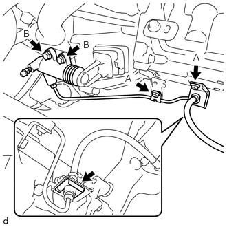
Install the clutch release cylinder assembly to the manual transaxle assembly with the 2 bolts B.
- Torque:
- 11.8 N*m (120 kgf*cm, 9 ft.*lbf)
Install the clutch release cylinder to flexible hose tube to the manual transaxle assembly with the 2 bolts A.
- Torque:
- 12 N*m (122 kgf*cm, 9 ft.*lbf)
Install a new clip.
82121
14.CONNECT ENGINE WIRE
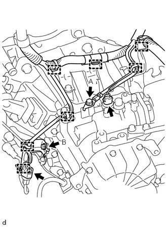
Install the wire harness clamp bracket to the manual transaxle assembly with the bolt B.
- Torque:
- for TMMIN Made : 12.5 N*m (127 kgf*cm, 9 ft.*lbf)
- for TMT Made : 13 N*m (133 kgf*cm, 10 ft.*lbf)
Engage the 7 clamps and install the engine wire to the wire harness clamp brackets.
Install the engine wire to the manual transaxle assembly with the bolt A.
- Torque:
- 12.8 N*m (131 kgf*cm, 9 ft.*lbf)
Connect the connector to the oxygen sensor.
Connect the connector to the back-up light switch assembly.
33820B
15.CONNECT TRANSMISSION CONTROL CABLE ASSEMBLY
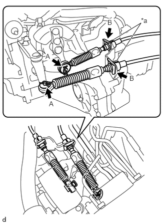
| *a | Paint Mark |
Install the transmission control cable assembly to the No. 1 transmission control cable bracket with 2 new clips B.
- NOTICE:
-
Make sure that the paint marks on the transmission control cable assembly are aligned with the slits in the No. 1 transmission control cable bracket before installing the clips.
Connect the transmission control cable assembly to the manual transaxle assembly with the 2 washers and 2 clips A.
74410
16.INSTALL BATTERY CARRIER ASSEMBLY
74431
17.INSTALL BATTERY TRAY
18.INSTALL BATTERY
17701
19.INSTALL AIR CLEANER CASE SUB-ASSEMBLY
17801
20.INSTALL AIR CLEANER FILTER ELEMENT SUB-ASSEMBLY
21.INSTALL AIR CLEANER CAP SUB-ASSEMBLY
17880
22.INSTALL AIR CLEANER HOSE ASSEMBLY
12262
23.CONNECT NO. 2 VENTILATION HOSE
24.CONNECT CABLE TO NEGATIVE BATTERY TERMINAL
- Torque:
- 5.4 N*m (55 kgf*cm, 48 in.*lbf)
- NOTICE:
-
When disconnecting the cable, some systems need to be initialized after the cable is reconnected.
-
Click hereGeneral>INTRODUCTION>REPAIR INSTRUCTION>INITIALIZATION
25.ADD MANUAL TRANSAXLE OIL
26.INSPECT MANUAL TRANSAXLE OIL
27.INSPECT FOR MANUAL TRANSAXLE OIL LEAK
28.INSPECT FOR EXHAUST GAS LEAK
- HINT:
-
Perform "Inspection After Repairs" after repairing gas leaks in the exhaust system.
-
Click hereEngine / Hybrid System>1NR-FE ENGINE CONTROL>SFI SYSTEM>INITIALIZATION