Home › Vehicle Interior › METER / GAUGE / DISPLAY › METER / GAUGE SYSTEM › from 2018.01
RM30M0E _58 Vehicle Interior _017113 METER / GAUGE / DISPLAY _0087658 METER / GAUGE SYSTEM J

METER / GAUGE / DISPLAY  METER / GAUGE SYSTEM  Steering Pad Switch Circuit  


DESCRIPTION

The combination meter assembly and steering pad switch assembly are connected via direct line. The main display and multi-information display in the combination meter assembly are operated using the switches of the steering pad switch assembly.

WIRING DIAGRAM
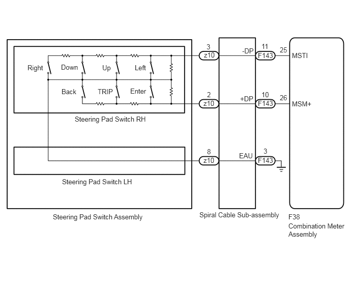
E373773E02
5.906,4.354 6.24,4.563 0.333,0.208 10 false F38 5.906,4.542 7.115,5.469 1.208,0.927 10 false Combination Meter Assembly 4.083,4.313 5.75,4.604 1.667,0.292 10 false Spiral Cable Sub-assembly 1.083,4.354 3.208,4.865 2.125,0.51 10 false Steering Pad Switch Assembly 5.281,3.198 5.677,3.396 0.396,0.198 10 false F143 5.281,2.031 5.677,2.229 0.396,0.198 10 false F143 5.281,1.052 5.677,1.25 0.396,0.198 10 false F143 4.167,3.198 4.427,3.438 0.26,0.24 10 false z10 4.958,0.958 5.26,1.156 0.302,0.198 10 false -DP 4.896,3.104 5.229,3.323 0.333,0.219 10 false EAU 4.917,1.938 5.25,2.156 0.333,0.219 10 false +DP 5.354,0.865 5.625,1.073 0.271,0.208 10 false 11 5.354,1.854 5.656,2.042 0.302,0.188 10 false 10 5.396,3.01 5.615,3.219 0.219,0.208 10 false 3 2.76,1.302 3.063,1.521 0.302,0.219 10 false Left 4.229,0.875 4.417,1.083 0.188,0.208 10 false 3 4.24,1.854 4.406,2.042 0.167,0.188 10 false 2 4.24,3.021 4.427,3.229 0.188,0.208 10 false 8 2.094,1.302 2.344,1.542 0.25,0.24 10 false Up 1.25,1.292 1.646,1.51 0.396,0.219 10 false Down 0.563,1.302 0.958,1.531 0.396,0.229 10 false Right 1.26,1.792 1.656,2.01 0.396,0.219 10 false Back 2,1.792 2.344,2 0.344,0.208 10 false TRIP 2.667,1.781 3.063,2 0.396,0.219 10 false Enter 1.531,2.354 3.25,2.625 1.719,0.271 10 false Steering Pad Switch RH 1.271,3.635 2.906,3.948 1.635,0.313 10 false Steering Pad Switch LH 5.729,0.938 6,1.146 0.271,0.208 10 false 25 5.729,1.917 5.969,2.135 0.24,0.219 10 false 26 5.979,2.042 6.49,2.292 0.51,0.25 10 false MSM+ 5.979,1.052 6.448,1.292 0.469,0.24 10 false MSTI 4.167,2.031 4.427,2.271 0.26,0.24 10 false z10 4.177,1.042 4.438,1.281 0.26,0.24 10 false z10

CAUTION / NOTICE / HINT

NOTICE:

When replacing the combination meter assembly, always replace it with a new one. If a combination meter assembly which was installed to another vehicle is used, the information stored in it will not match the information from the vehicle and a DTC may be stored.


PROCEDURE

1.INSPECT STEERING PAD SWITCH ASSEMBLY
a.

Remove the steering pad switch assembly.

Click hereAudio / Visual / Telematics>AUDIO / VIDEO>STEERING PAD SWITCH>REMOVAL


b.

Inspect the steering pad switch assembly.

Click hereAudio / Visual / Telematics>AUDIO / VIDEO>STEERING PAD SWITCH>INSPECTION


Result:
Proceed to
OK
NG


OK

2.INSPECT SPIRAL CABLE SUB-ASSEMBLY

NG

REPLACE STEERING PAD SWITCH ASSEMBLY

2.INSPECT SPIRAL CABLE SUB-ASSEMBLY
a.

Remove the spiral cable sub-assembly.

Click hereVehicle Interior>SUPPLEMENTAL RESTRAINT SYSTEMS>SPIRAL CABLE>REMOVAL


b.

Inspect the spiral cable sub-assembly.

Click hereVehicle Interior>SUPPLEMENTAL RESTRAINT SYSTEMS>SPIRAL CABLE>INSPECTION


Result:
Proceed to
OK
NG


OK

3.CHECK HARNESS AND CONNECTOR (SPIRAL CABLE SUB-ASSEMBLY - COMBINATION METER ASSEMBLY)

NG

REPLACE SPIRAL CABLE SUB-ASSEMBLY

3.CHECK HARNESS AND CONNECTOR (SPIRAL CABLE SUB-ASSEMBLY - COMBINATION METER ASSEMBLY)
a.

Disconnect the F38 combination meter assembly connector.


b.

Disconnect the F143 spiral cable sub-assembly connector.


c.

Measure the resistance according to the value(s) in the table below.

Standard Resistance:
Tester Connection Condition Specified Condition
F38-25 (MSTI) - F143-11 (-DP) Always Below 1 Ω
F38-26 (MSM+) - F143-10 (+DP) Always Below 1 Ω
F143-3 (EAU) - Body ground Always Below 1 Ω
F38-25 (MSTI) or F143-11 (-DP) - Body ground Always 10 kΩ or higher
F38-26 (MSM+) or F143-10 (+DP) - Body ground Always 10 kΩ or higher


Result:
Proceed to
OK
NG


OK

REPLACE COMBINATION METER ASSEMBLY

NG

REPAIR OR REPLACE HARNESS OR CONNECTOR