METER / GAUGE / DISPLAY COMBINATION METER REMOVAL
CAUTION / NOTICE / HINT
The necessary procedures (adjustment, calibration, initialization or registration) that must be performed after parts are removed and installed, or replaced during combination meter assembly removal/installation are shown below.
| Replaced Part or Performed Procedure | Necessary Procedures | Effect/Inoperative Function When Necessary Procedures are not Performed | Link |
|---|---|---|---|
| Disconnect cable from negative (-) auxiliary battery terminal | Memorize steering angle neutral point | Parking assist monitor system | ( ) |
- HINT:
-
When the cable is disconnected/reconnected to the auxiliary battery terminal, systems temporarily stop operating. However, each system has a function that completes learning the first time the system is used.
- ·
Learning completes when vehicle is driven
Effect/Inoperative Function When Necessary Procedures are not Performed Necessary Procedures Link Lane tracing assist system Drive the vehicle straight ahead at 35 km/h (22 mph) or more for 5 second or more. ( )
Pre-collision system
·Learning completes when vehicle is operated normally
Effect/Inoperative Function When Necessary Procedures are not Performed Necessary Procedures Link Power door lock control system
·Back door opener
Perform door unlock operation with door control switch or electrical key transmitter sub-assembly switch. ( )
Air conditioning system After the ignition switch is turned to ON, the servo motor standard position is recognized. -
PROCEDURE

 1. PRECAUTION
- NOTICE:
-
After the ignition switch is turned off, there may be a waiting time before disconnecting the negative (-) auxiliary battery terminal.
-
Click hereGeneral>SETUP>WHEN DISCONNECTING OR RECONNECTING BATTERY TERMINAL>BEFORE DISCONNECTING BATTERY
2.DISCONNECT CABLE FROM NEGATIVE AUXILIARY BATTERY TERMINAL
for Gasoline Model:
Click hereGeneral>MAINTENANCE>M15A-FKS AUXILIARY BATTERY>REMOVAL
for HV Model:
Click hereGeneral>MAINTENANCE>M15A-FXE AUXILIARY BATTERY>REMOVAL
55479D
3.REMOVE LOWER INSTRUMENT CLUSTER FINISH PANEL GARNISH
55432B
4.REMOVE LOWER INSTRUMENT PANEL FINISH PANEL
55407B
5.REMOVE SWITCH HOLE BASE SUB-ASSEMBLY
33504F
6.REMOVE SHIFT LEVER KNOB SUB-ASSEMBLY (for CVT)
33504F
7.REMOVE SHIFT LEVER KNOB SUB-ASSEMBLY (for Manual Transaxle)
33554
8.REMOVE SHIFT LEVER CAP (for CVT)
58802E
9.REMOVE FRONT CONSOLE BOX SUB-ASSEMBLY
67913B
10.REMOVE FRONT DOOR SCUFF PLATE RH
62111C
11.REMOVE COWL SIDE TRIM BOARD RH
62311B
12.DISCONNECT FRONT DOOR OPENING TRIM WEATHERSTRIP RH
55317E
13.REMOVE NO. 1 INSTRUMENT SIDE PANEL
55606
14.REMOVE NO. 1 INSTRUMENT PANEL UNDER COVER SUB-ASSEMBLY
53601
15.DISCONNECT HOOD LOCK CONTROL LEVER SUB-ASSEMBLY
55480D
16.REMOVE LOWER INSTRUMENT PANEL FINISH PANEL ASSEMBLY
55410C
17.REMOVE INSTRUMENT CLUSTER FINISH PANEL ASSEMBLY (for Analog Meter)
55410C
18.REMOVE INSTRUMENT CLUSTER FINISH PANEL ASSEMBLY (for Digital Meter)
83100
19.REMOVE COMBINATION METER ASSEMBLY (for Analog Meter)
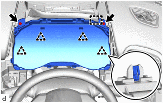
Remove the 2 screws.
Disengage the clips and guide.
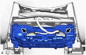
Disconnect the 2 connectors to remove the combination meter assembly.
83100
20.REMOVE COMBINATION METER ASSEMBLY (for Digital Meter)
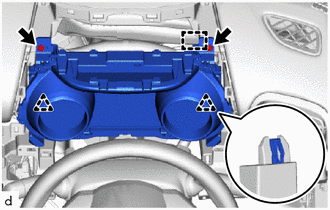
Remove the 2 screws.
Disengage the clips and guide.
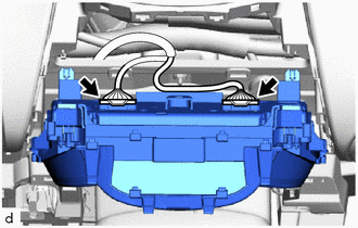
Disconnect the 2 connectors to remove the combination meter assembly.