INTERIOR PANELS / TRIM INSTRUMENT PANEL SAFETY PAD REMOVAL
CAUTION / NOTICE / HINT
The necessary procedures (adjustment, calibration, initialization or registration) that must be performed after parts are removed and installed, or replaced during instrument panel sub-assembly removal/installation are shown below.
| Replacement Part or Procedure | Necessary Procedures | Effect/Inoperative Function When Necessary Procedures are not Performed | Link |
|---|---|---|---|
| Disconnect cable from negative (-) auxiliary battery terminal | Memorize steering angle neutral point | Parking assist monitor system | ( ) |
- CAUTION:
-
-
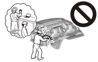
Some of these service operations affect the SRS airbag system. Read the precautionary notices concerning the SRS airbag system before servicing.
-
Click hereVehicle Interior>SUPPLEMENTAL RESTRAINT SYSTEMS>AIRBAG SYSTEM>PRECAUTION
- HINT:
-
When the cable is disconnected/reconnected to the auxiliary battery terminal, systems temporarily stop operating. However, each system has a function that completes learning the first time the system is used.
- ·
Learning completes when vehicle is driven
Effect/Inoperative Function When Necessary Procedures are not Performed Necessary Procedures Link Lane tracing assist system Drive the vehicle straight ahead at 35 km/h (22 mph) or more for 5 second or more. ( )
Pre-collision system
·Learning completes when vehicle is operated normally
Effect/Inoperative Function When Necessary Procedures are not Performed Necessary Procedures Link Power door lock control system
·Back door opener
Perform door unlock operation with door control switch or electrical key transmitter sub-assembly switch. ( )
Air conditioning system After the ignition switch is turned to ON, the servo motor standard position is recognized. -
PROCEDURE

 1. PRECAUTION
- NOTICE:
-
After the ignition switch is turned off, there may be a waiting time before disconnecting the negative (-) auxiliary battery terminal.
-
Click hereGeneral>SETUP>WHEN DISCONNECTING OR RECONNECTING BATTERY TERMINAL>BEFORE DISCONNECTING BATTERY
2. TABLE OF BOLT, SCREW AND NUT
- HINT:
-
All bolts and screws relevant to installing and removing the instrument panel are shown along with their alphabetic code in the table below.
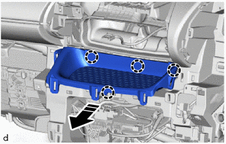
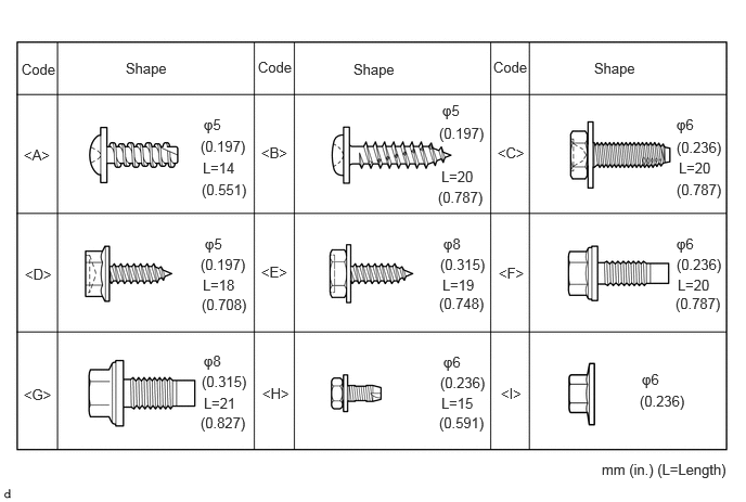 0.208,0.583 0.823,0.781 0.615,0.198 10 false Code 2.479,0.563 3.094,0.76 0.615,0.198 10 false Code 4.74,0.563 5.354,0.76 0.615,0.198 10 false Code 1.208,0.573 1.823,0.771 0.615,0.198 10 false Shape 3.396,0.583 4.01,0.781 0.615,0.198 10 false Shape 5.708,0.573 6.323,0.771 0.615,0.198 10 false Shape 0.229,1.406 0.844,1.604 0.615,0.198 10 false <A> 0.24,2.552 0.854,2.75 0.615,0.198 10 false <D> 0.229,3.708 0.844,3.906 0.615,0.198 10 false <G> 2.51,1.385 3.125,1.583 0.615,0.198 10 false <B> 2.51,2.531 3.125,2.729 0.615,0.198 10 false <E> 2.521,3.698 3.135,3.896 0.615,0.198 10 false <H> 4.781,1.385 5.396,1.583 0.615,0.198 10 false <C> 4.792,2.542 5.406,2.74 0.615,0.198 10 false <F> 4.813,3.698 5.427,3.896 0.615,0.198 10 false <I> 5.781,4.427 7.073,4.677 1.292,0.25 10 false mm (in.) (L=Length) 1.927,1.323 2.448,1.552 0.521,0.229 10 false (0.197) 1.958,1.115 2.271,1.313 0.313,0.198 10 false φ5 1.948,1.531 2.365,1.729 0.417,0.198 10 false L=14 1.938,1.74 2.458,1.969 0.521,0.229 10 false (0.551) 1.969,2.26 2.281,2.458 0.313,0.198 10 false φ5 1.927,2.458 2.448,2.688 0.521,0.229 10 false (0.197) 4.25,2.656 4.698,2.854 0.448,0.198 10 false L=19 1.938,2.844 2.458,3.073 0.521,0.229 10 false (0.708) 1.958,3.385 2.271,3.583 0.313,0.198 10 false φ8 1.938,3.583 2.458,3.813 0.521,0.229 10 false (0.315) 1.958,3.792 2.406,3.99 0.448,0.198 10 false L=21 1.927,3.979 2.448,4.208 0.521,0.229 10 false (0.827) 4.25,0.979 4.563,1.177 0.313,0.198 10 false φ5 4.219,1.198 4.74,1.427 0.521,0.229 10 false (0.197) 4.24,1.615 4.656,1.813 0.417,0.198 10 false L=20 4.208,1.813 4.729,2.042 0.521,0.229 10 false (0.787) 4.26,2.26 4.573,2.458 0.313,0.198 10 false φ8 4.229,2.458 4.75,2.688 0.521,0.229 10 false (0.315) 1.948,2.656 2.396,2.854 0.448,0.198 10 false L=18 4.219,2.833 4.74,3.063 0.521,0.229 10 false (0.748) 4.26,3.396 4.573,3.594 0.313,0.198 10 false φ6 4.229,3.594 4.75,3.823 0.521,0.229 10 false (0.236) 4.24,3.792 4.688,3.99 0.448,0.198 10 false L=15 4.219,3.979 4.74,4.208 0.521,0.229 10 false (0.591) 6.167,3.563 6.479,3.76 0.313,0.198 10 false φ6 6.146,3.771 6.667,4 0.521,0.229 10 false (0.236) 6.5,2.26 6.813,2.458 0.313,0.198 10 false φ6 6.5,2.458 7.021,2.688 0.521,0.229 10 false (0.236) 6.51,2.656 6.927,2.854 0.417,0.198 10 false L=20 6.49,2.833 7.01,3.063 0.521,0.229 10 false (0.787) 6.5,1.115 6.813,1.313 0.313,0.198 10 false φ6 6.5,1.333 7.021,1.563 0.521,0.229 10 false (0.236) 6.521,1.531 6.938,1.729 0.417,0.198 10 false L=20 6.5,1.74 7.021,1.969 0.521,0.229 10 false (0.787)
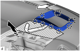
3.DISCONNECT CABLE FROM NEGATIVE AUXILIARY BATTERY TERMINAL
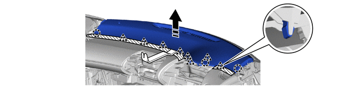
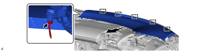
for Gasoline Model:
Click hereGeneral>MAINTENANCE>M15A-FKS AUXILIARY BATTERY>REMOVAL
for HV Model:
Click hereGeneral>MAINTENANCE>M15A-FXE AUXILIARY BATTERY>REMOVAL
4.REMOVE REAR CONSOLE BOX ASSEMBLY
5.REMOVE HEADLIGHT DIMMER SWITCH ASSEMBLY
67913B
6.REMOVE FRONT DOOR SCUFF PLATE RH
67914B
7.REMOVE FRONT DOOR SCUFF PLATE LH
- HINT:
-
Use the same procedure as for the RH side.
62111C
8.REMOVE COWL SIDE TRIM BOARD RH
62112
9.REMOVE COWL SIDE TRIM BOARD LH
- HINT:
-
Use the same procedure as for the RH side.
55606
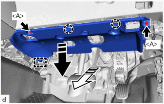
10.REMOVE NO. 1 INSTRUMENT PANEL UNDER COVER SUB-ASSEMBLY

|
Remove in this Direction (1) |

|
Remove in this Direction (2) |
Remove the 2 screws <A>.
Disengage the claws and guide to remove the No. 1 instrument panel under cover sub-assembly as shown in the illustration.
55607
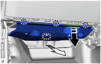
11.REMOVE NO. 2 INSTRUMENT PANEL UNDER COVER SUB-ASSEMBLY
|
|
Remove in this Direction (1) |
|
|
Remove in this Direction (2) |
Disengage the claws and guide to remove the No. 2 instrument panel under cover sub-assembly as shown in the illustration.
62311B
12.DISCONNECT FRONT DOOR OPENING TRIM WEATHERSTRIP RH
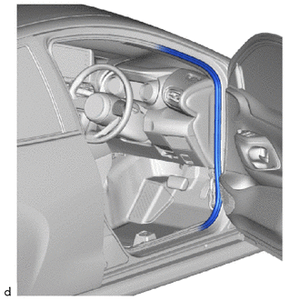
Disconnect the front door opening trim weatherstrip RH from the area shown in the illustration.
62312B
13.DISCONNECT FRONT DOOR OPENING TRIM WEATHERSTRIP LH
- HINT:
-
Use the same procedure as for the RH side.
55317E
14.REMOVE NO. 1 INSTRUMENT SIDE PANEL
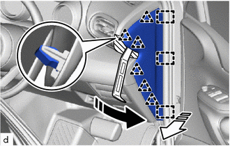

|
Protective Tape |
|
|
Remove in this Direction (1) |
|
|
Remove in this Direction (2) |
Using a molding remover A, disengage the clips and guides to remove the No. 1 instrument side panel as shown in the illustration.
55318F
15.REMOVE NO. 2 INSTRUMENT SIDE PANEL
- HINT:
-
Use the same procedure as for the No. 1 side.
55550
16.REMOVE GLOVE COMPARTMENT DOOR ASSEMBLY
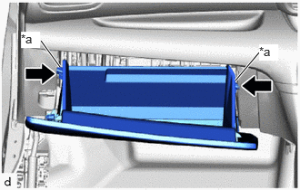
| *a | Stopper |

|
Push |
Disengage the 2 stoppers and pull out the glove compartment door assembly until it is level.
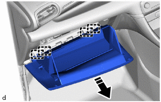
|
|
Remove in this Direction |
Disengage the hinges to remove the glove compartment door assembly as shown in the illustration.
55433B
17.REMOVE LOWER NO. 2 INSTRUMENT PANEL FINISH PANEL
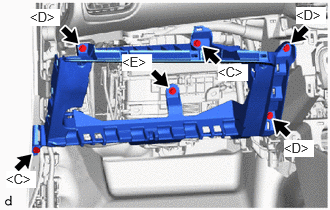
Remove the 2 screws <C>, 3 screws <D> and screw <E>.
|
|
Remove in this Direction |
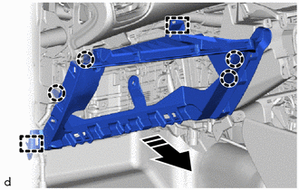
Disengage the claws and guides to remove the lower No. 2 instrument panel finish panel as shown in the illustration.
55557A
18.REMOVE GLOVE COMPARTMENT DOOR CHECK CUSHION
- HINT:
-
Use the same procedure as for the opposite side.
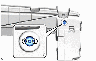
Disengage the claws to remove the glove compartment door check cushion.
62211
19.REMOVE FRONT PILLAR GARNISH RH
|
|
Pull up |
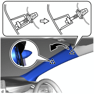
Pull up the front pillar garnish RH to disengage the front pillar garnish clip and clip as shown in the illustration.
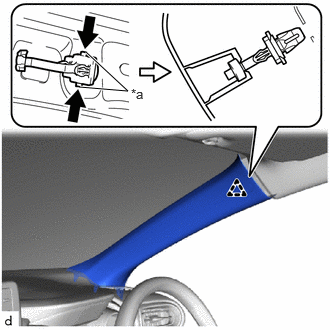
| *a | Release Lever |
|
|
Push |
Push the release lever and separate the front pillar garnish clip from the vehicle body as shown in the illustration.
When the front pillar garnish clip cannot be removed using your fingers:
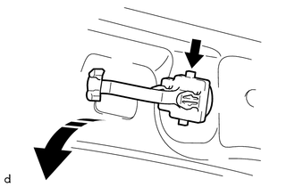
|
|
Lift in this Direction |
While pressing the part shown in the illustration with your finger, move the front pillar garnish clip in the direction indicated by the arrow shown in the illustration.
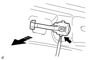
|
|
Remove in this Direction |
While pulling the front pillar garnish clip in the direction indicated by the arrow, push the part shown in the illustration with the end of a screwdriver and remove the front pillar garnish clip.
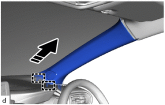
|
|
Remove in this Direction |
Disengage the guides as shown in the illustration.
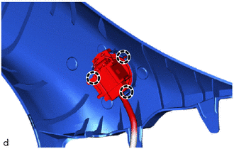
w/ Speaker:
Disengage the claws to disconnect the front No.2 speaker assembly and remove the front pillar garnish RH.
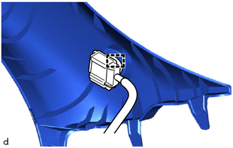
w/o Speaker:
Disengage the clamp to remove the front pillar garnish RH.
Remove the front pillar garnish clip from the front pillar garnish RH.
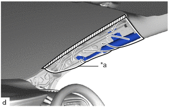
| *a | Protective Cover |
|
|
Adhesive Tape |
Protect the curtain shield airbag assembly.
Completely cover the curtain shield airbag assembly with a cloth or nylon sheet and secure the ends of the cover with adhesive tape as shown in the illustration.
- NOTICE:
-
Cover the curtain shield airbag assembly with a protective cover as soon as the front pillar garnish RH is removed.
62212
20.REMOVE FRONT PILLAR GARNISH LH
- HINT:
-
Use the same procedure as for the RH side.
86160P
21.REMOVE FRONT NO. 2 SPEAKER ASSEMBLY (for 6 Speakers)
53601
22.DISCONNECT HOOD LOCK CONTROL LEVER SUB-ASSEMBLY
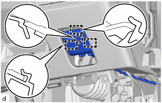
Disengage the claw and guides to disconnect the hood lock control lever sub-assembly.
55480D
23.REMOVE LOWER INSTRUMENT PANEL FINISH PANEL ASSEMBLY
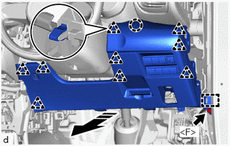
|
|
Remove in this Direction |
Remove the bolt <F>.
Disengage the clips, claw and guide to remove the lower instrument panel finish panel assembly as shown in the illustration.
Disconnect each connector.
55548A
24.REMOVE INSTRUMENT PANEL HOLE COVER
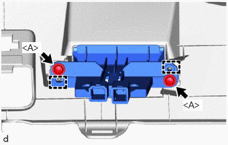
Remove the 2 screws <A>.
Disengage the guides to remove the instrument panel hole cover.
55410C
25.REMOVE INSTRUMENT CLUSTER FINISH PANEL ASSEMBLY (for Analog Meter)
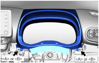
Remove the 2 screws <A> or 2 screws <B>.
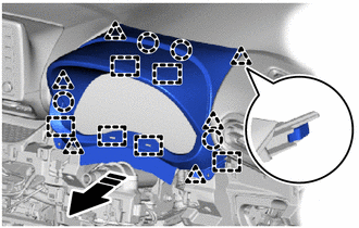
|
|
Remove in this Direction |
Disengage the clips, claws and guides to remove the instrument cluster finish panel assembly as shown in the illustration.
55410C
26.REMOVE INSTRUMENT CLUSTER FINISH PANEL ASSEMBLY (for Digital Meter)
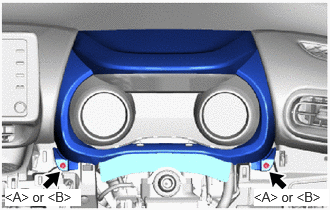
Remove the 2 screws <A> or 2 screws <B>.
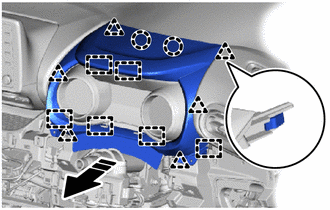
|
|
Remove in this Direction |
Disengage the clips, claws and guides to remove the instrument cluster finish panel assembly as shown in the illustration.
83100
27.REMOVE COMBINATION METER ASSEMBLY (for Analog Meter)
83100
28.REMOVE COMBINATION METER ASSEMBLY (for Digital Meter)
55406B
29.REMOVE INSTRUMENT CLUSTER FINISH LOWER CENTER PANEL SUB-ASSEMBLY (for Manual Air Conditioning System)
55900
30.REMOVE AIR CONDITIONING CONTROL ASSEMBLY (for Automatic Air Conditioning System)
55405B
31.REMOVE INSTRUMENT CLUSTER FINISH CENTER PANEL SUB-ASSEMBLY
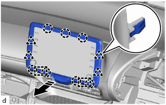
|
|
Remove in this Direction |
Disengage the clips, claws and guides to remove the instrument cluster finish center panel sub-assembly as shown in the illustration.
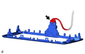
Disconnect the connector.
55670A
32.REMOVE INSTRUMENT PANEL CENTER REGISTER ASSEMBLY
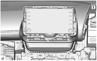
|
|
Protective Tape |
Apply protective tape to the locations shown in the illustration.
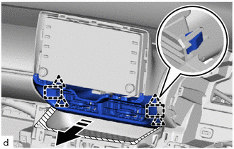
|
|
Remove in this Direction |
Disengage the clips and guides as shown in the illustration.
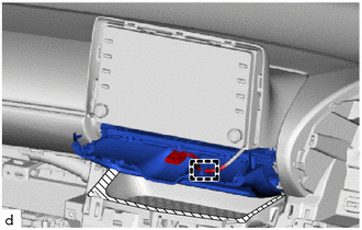
Disengage the clamp to remove the instrument panel center register assembly.
86140A
33.REMOVE RADIO AND DISPLAY RECEIVER ASSEMBLY WITH BRACKET
55420A
34.REMOVE INSTRUMENT CLUSTER FINISH CENTER PANEL ASSEMBLY
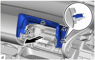
|
|
Remove in this Direction |
Disengage the clips to remove the instrument cluster finish center panel assembly as shown in the illustration.
55624A
35.REMOVE INSTRUMENT PANEL CENTER TRAY
|
|
Remove in this Direction |
Disengage the claws to remove the instrument panel center tray as shown in the illustration.
55414A
36.REMOVE INSTRUMENT CLUSTER FINISH END PANEL (w/ Headup Display)
|
|
Protective Tape |
|
|
Remove in this Direction (1) |
|
|
Remove in this Direction (2) |
Using a molding remover A, disengage the claws and guides to remove the instrument cluster finish end panel as shown in the illustration.
55313A
37.REMOVE INSTRUMENT MAIN PANEL (for Separate Type)
Using a molding remover B, disengage the clips and claws as shown in the illustration.
|
|
Protective Tape |
|
Remove in this Direction |
Disconnect the connector.
|
|
Remove in this Direction | - | - |
Disengage the guides to remove the instrument main panel as shown in the illustration.
55302C
38.REMOVE INSTRUMENT PANEL SUB-ASSEMBLY (for Integrated Type)
Disconnect the connector.
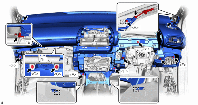
| *a | Airbag Connector | *b | Airbag Bolt |
Remove the bolt <H> and disengage the guide to separate the ground bracket.
Remove the 2 bolts <G>.
Disconnect the airbag connector.
- NOTICE:
-
When disconnecting any airbag connector, take care not to damage the airbag wire harness.
- HINT:
-
Refer to How to Connect or Disconnect Airbag Connector:
Remove the 4 clips.
Disengage the hooks.
Remove the 3 bolts <F>, screw <E> and nut <I> as shown in the illustration.
Disengage the guides to remove the instrument panel sub-assembly as shown in the illustration.
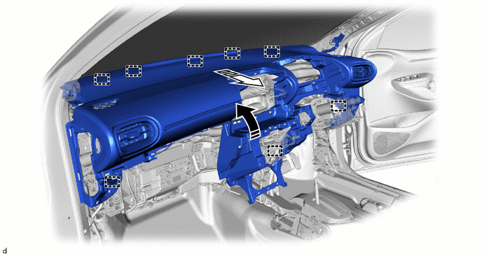
|
|
Remove in this Direction (1) |
|
Remove in this Direction (2) |
55302C
39.REMOVE INSTRUMENT PANEL SUB-ASSEMBLY (for Separate Type)
Disconnect the connector.
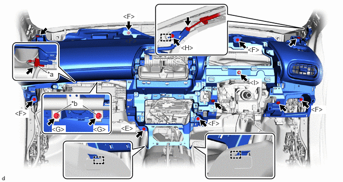
| *a | Airbag Connector | *b | Airbag Bolt |
Remove the bolt <H> and disengage the guide to separate the ground bracket.
Remove the 2 bolts <G>.
Disconnect the airbag connector.
- NOTICE:
-
When disconnecting any airbag connector, take care not to damage the airbag wire harness.
- HINT:
-
Refer to How to Connect or Disconnect Airbag Connector:
Remove the 4 clips.
Disengage the hooks.
Remove the 5 bolts <F>, screw <E> and nut <I> as shown in the illustration.
Disengage the guides to remove the instrument panel sub-assembly as shown in the illustration.
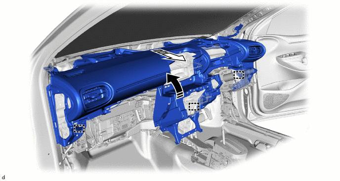
|
|
Remove in this Direction (1) |
|
Remove in this Direction (2) |
55950G
40.REMOVE DEFROSTER NOZZLE ASSEMBLY (for Separate Type)
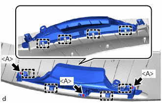
Remove the 3 screws <A>.
Disengage the guides to remove the defroster nozzle assembly.
89120A
41.REMOVE AUTOMATIC LIGHT CONTROL SENSOR (for Separate Type)
55328
42.REMOVE NO. 1 INSTRUMENT PANEL PIN (for Separate Type)
- HINT:
-
Use the same procedure as for the opposite side.
Remove the screw <A>.
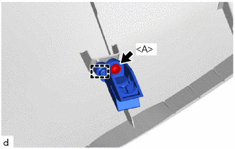
Disengage the guide to remove the No. 1 instrument panel pin.