CLUTCH CLUTCH PEDAL SWITCH INSTALLATION
PROCEDURE

 88280A
1.INSTALL CLUTCH SWITCH ASSEMBLY
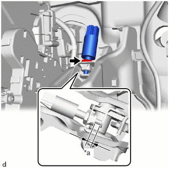
| *a | Clearance |
Install the clutch switch assembly to the clutch pedal support sub-assembly with the nut.
- Torque:
- 15.7 N*m (160 kgf*cm, 12 ft.*lbf)
Connect the clutch switch assembly connector.
Without depressing the clutch pedal, check that the clearance shown in the illustration is as specified.
- Standard clearance:
1.8 to 2.8 mm (0.071 to 0.110 in.)
2.INSTALL CLUTCH PEDAL SUPPORT ASSEMBLY
31453A
3.INSTALL CLUTCH MASTER CYLINDER PUSH ROD CLEVIS WITH HOLE PIN
4.INSTALL STEERING COLUMN ASSEMBLY
84520
5.INSTALL CLUTCH START SWITCH ASSEMBLY
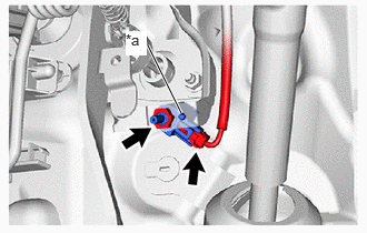
| *a | Protrusion |
Install the clutch start switch assembly to the clutch pedal support sub-assembly with the nut.
- Torque:
- 15.7 N*m (160 kgf*cm, 12 ft.*lbf)
- NOTICE:
- ·
Insert the protrusion of the clutch start switch assembly into the hole in the clutch pedal support sub-assembly.
·To prevent damage to the clutch start switch assembly, make sure not to rotate it during installation.
Connect the clutch start switch assembly connector.
55606
6.INSTALL NO. 1 INSTRUMENT PANEL UNDER COVER SUB-ASSEMBLY
7.INSPECT CLUTCH START SYSTEM
8. INITIALIZATION AFTER RECONNECTING BATTERY TERMINAL
Click hereGeneral>SETUP>WHEN DISCONNECTING OR RECONNECTING BATTERY TERMINAL>WORK PROCEDURE
- HINT:
-
When disconnecting and reconnecting the battery, there is an automatic learning function that completes learning when the respective system is used.
-
Click hereGeneral>SETUP>WHEN DISCONNECTING OR RECONNECTING BATTERY TERMINAL>AUTOMATIC LEARNING CHART