1KR-FE ENGINE CONTROL SFI SYSTEM P210900 Throttle / Pedal Position Sensor "A" Minimum Stop Performance P210956 Throttle/Pedal Position Sensor "A" Minimum Stop Performance Invalid/Incompatible Configuration
DESCRIPTION
The idle speed is controlled by the Electronic Throttle Control System (ETCS). The ETCS is comprised of a throttle actuator, which operates the throttle valve, and a throttle position sensor, which detects the opening amount of the throttle valve. The ECM controls the throttle actuator to adjust the throttle valve opening amount so that the idle speed is maintained at the target idle speed.
| DTC No. | Detection Item | DTC Detection Condition | Trouble Area | MIL | Memory | DTC Output from | Priority |
|---|---|---|---|---|---|---|---|
| P210900 | Throttle / Pedal Position Sensor "A" Minimum Stop Performance | When the target throttle flow volume is within the range of 13 to 16 kg/h and the difference with the standard flow volume characteristics is -2.8 (kg/h) or less (1 trip detection logic) | Throttle body with motor assembly | - | DTC stored | Engine | B |
| P210956 | Throttle/Pedal Position Sensor "A" Minimum Stop Performance Invalid/Incompatible Configuration | When the voltage during the initial electronic throttle fully closed position learning is one of the following
·
Sensor 1 voltage below 0.33 V ·
Sensor 2 voltage higher than 4.67 V ·
[5 V - (sensor 1 voltage + sensor 2 voltage)] (absolute value) is equal to or greater than 0.12 V Or when the voltage of the initial electronic throttle fully closed position learning is one of the following ·
Sensor 1 voltage higher than 0.68 V ·
Sensor 2 voltage below 4.32 V (1 trip detection logic) |
Throttle body with motor assembly | Comes on | DTC stored | Engine | B |
- HINT:
- ·
Detection for P210900 and P210956 are performed during electronic throttle learning. (The learning can be performed using the GTS)
·This malfunction is detected only once per trip. After it has been detected once, the ECM will stop monitoring for the malfunction for the rest of the trip (when deposits in the throttle body with motor assembly are detected).
·The system uses the throttle body with motor assembly to detect this malfunction (when deposits in the throttle body are detected).
WIRING DIAGRAM
Refer to DTC P01201C.
Click hereEngine / Hybrid System>1KR-FE (ENGINE CONTROL)>SFI SYSTEM>P01201C
CAUTION / NOTICE / HINT
- NOTICE:
-
After replacing the throttle body with motor assembly, perform electronic throttle learning and idle learning.
-
Click hereEngine / Hybrid System>1KR-FE (ENGINE CONTROL)>SFI SYSTEM>INITIALIZATION
- HINT:
-
Read freeze frame data using the GTS. Freeze frame data records the engine condition when malfunctions are detected. When troubleshooting, freeze frame data can help determine if the vehicle was moving or stationary, if the engine was warmed up or not, if the air fuel ratio was lean or rich, and other data from the time the malfunction occurred.
PROCEDURE
Read the DTCs.
- Powertrain > Engine > Trouble Codes
- 50001 372
- Result:
Result Proceed to Only P210900, P210954 or P210956 is output A P210900 or P210956 and other DTCs are output B
- HINT:
-
If any DTCs other than P210900 or P210956 are output, troubleshoot those DTCs first.
A
B
- OK:
Learning is complete.
- Result:
Proceed to OK NG
OK
NG
Read the DTCs.
- Powertrain > Engine > Trouble Codes
- 50001 372
- Result:
Result Proceed to Only P210900 or P210956 is output A P210900 or P210956 and other DTCs are output B
- HINT:
-
If any DTCs other than P210900 or P210956 are output, troubleshoot those DTCs first.
A
B
Read the value when the accelerator pedal is operated.
- Powertrain > Engine > Data List
-
Tester Display Throttle Sensor Position - 50003 372 308
- OK:
The throttle position sensor value varies with changes in the angle of the accelerator pedal.
- Result:
Proceed to OK NG
OK
NG
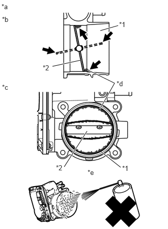
| *1 | Bore |
| *2 | Valve |
| *a | Reference |
| *b | Throttle Body with Motor Assembly Cross-section Diagram |
| *c | When valve fully opened |
| *d | Deposits |
| *e | Do not directly apply cleaner |
Clean off any deposits from the inside of the throttle body assembly.
Push open the throttle valve and wipe off any carbon from the valve and bore using a piece of cloth soaked in non-residue solvent.
- NOTICE:
- ·
Make sure that the cloth or your fingers do not get caught in the valve.
·Make sure that foreign matter does not enter the throttle valve.
·Do not directly apply non-residue solvent to the throttle body assembly or wash the throttle body with motor assembly. Cleaning solvent may leak into the motor from the shaft and cause problems such as rust or valve movement problems.
·If there is coating material on the edge of the valve, be careful not to remove it.
·Push the throttle valve open gently with your finger and check that the throttle valve moves smoothly.
- HINT:
-
If the throttle valve does not move smoothly, replace the throttle body assembly.
- Result:
Proceed to NEXT
NEXT
Pre-procedure1
Perform electronic throttle learning.
Start the engine and warm it up until the engine coolant temperature is 80°C (176°F) or higher.
After the engine is warmed up, allow it to idle for 5 minutes with the air conditioning and all accessories off.
Procedure1
Confirm that the idle speed is within the specified range.
- Powertrain > Engine > Data List
-
Tester Display Engine Speed - 50003 372 211
- OK:
790 to 940 rpm
- HINT:
- ·
Be sure to perform this step with all accessories off.
·Make sure that the shift lever is in neutral.
- Result:
Result Proceed to The value of Engine Speed is between 790 and 940 rpm A None of the above conditions are met B
Post-procedure1
None.
A
B