C551 MANUAL TRANSMISSION / TRANSAXLE MANUAL TRANSAXLE ASSEMBLY(When Not Using the Engine Support Bridge) INSTALLATION
PROCEDURE

 33111A
1.INSTALL MANUAL TRANSMISSION CASE PLUG
Install a new gasket and manual transaxle case plug to the manual transaxle assembly.
- Torque:
- 39.2 N*m (400 kgf*cm, 29 ft.*lbf)
2.INSTALL WIRE HARNESS CLAMP BRACKET
Install the 2 wire harness clamp brackets to the manual transaxle assembly with the 2 bolts.
- Torque:
- 20 N*m (204 kgf*cm, 15 ft.*lbf)
33544C
3.INSTALL SHIFT LEVER DAMPER
Install the shift lever damper to the manual transaxle assembly with the 2 nuts.
- Torque:
- 20 N*m (204 kgf*cm, 15 ft.*lbf)
30300
4.INSTALL MANUAL TRANSAXLE ASSEMBLY
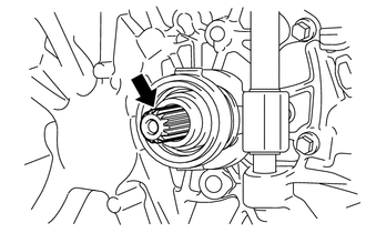

|
Clutch Spline Grease |
Apply clutch spline grease to the input shaft spline.
- Grease:
Toyota Genuine Clutch Spline Grease or equivalent
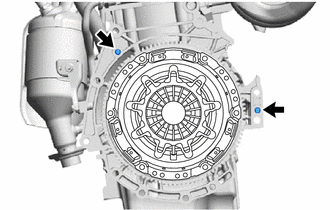
Confirm that the 2 knock pins are installed on the engine assembly and are not damaged.
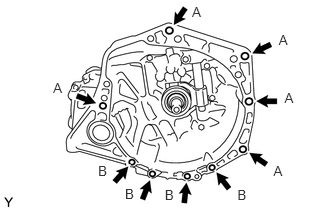
Align the input shaft with the clutch disc and install the manual transaxle assembly to the engine assembly.
Install the 9 bolts.
- Torque:
- Bolt A : 64 N*m (653 kgf*cm, 47 ft.*lbf)
- Bolt B : 39 N*m (398 kgf*cm, 29 ft.*lbf)
- NOTICE:
- ·
Make sure that the wire harness or similar items are not pinched between the contact surfaces.
·Do not forcibly pry on the manual transaxle assembly.
·When mounting the manual transaxle assembly to the engine assembly, make sure to securely fit the knock pins into the knock holes.
·When tightening the bolts, be sure that the contact surfaces of the engine assembly and manual transaxle assembly are in close contact with one another.
12325A
5.INSTALL ENGINE MOUNTING BRACKET LH
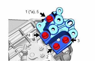
| *a | Temporarily Tighten |
Install the engine mounting bracket LH to the manual transaxle assembly with the 4 bolts in the order shown in the illustration.
- Torque:
- 42 N*m (428 kgf*cm, 31 ft.*lbf)
6.INSTALL ENGINE MOVING CONTROL ROD BRACKET
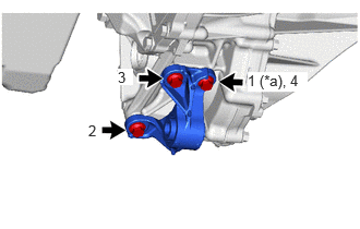
| *a | Temporarily Tighten |
Install the engine moving control rod bracket to the manual transaxle assembly with the 3 bolts in the order shown in the illustration.
- Torque:
- 44 N*m (449 kgf*cm, 32 ft.*lbf)
51201
7.INSTALL FRONT SUSPENSION CROSSMEMBER SUB-ASSEMBLY
11363A
8.INSTALL FLYWHEEL HOUSING SIDE COVER
43409E
9.INSTALL DRIVE SHAFT HEAT INSULATOR SUB-ASSEMBLY
82121
10.CONNECT ENGINE WIRE
Engage the 2 clamps to install the engine wire to the wire harness clamp brackets.
Connect the back-up light switch assembly connector.
w/ Stop and Start System:
Install the engine wire protector with the 2 bolts.
- Torque:
- 20 N*m (204 kgf*cm, 15 ft.*lbf)
Install the engine wire with the bolt.
- Torque:
- 10 N*m (102 kgf*cm, 7 ft.*lbf)
Connect the neutral position switch connector.