C551 MANUAL TRANSMISSION / TRANSAXLE MANUAL TRANSAXLE ASSEMBLY(When Using the Engine Support Bridge) INSTALLATION
CAUTION / NOTICE / HINT
- NOTICE:
-
When the manual transaxle assembly is removed, be sure to use a new clutch release with bearing cylinder assembly and new installation bolts. Removal of the manual transaxle assembly allows the compressed clutch release with bearing cylinder assembly to return to its original position. Dust from the moving section may damage the seal of the clutch release with bearing cylinder assembly, possibly causing clutch fluid leaks.
PROCEDURE

 33111A
1.INSTALL MANUAL TRANSMISSION CASE PLUG
Install a new gasket and manual transaxle case plug to the manual transaxle assembly.
- Torque:
- 39.2 N*m (400 kgf*cm, 29 ft.*lbf)
2.INSTALL WIRE HARNESS CLAMP BRACKET
Install the 2 wire harness clamp brackets to the manual transaxle assembly with the 2 bolts.
- Torque:
- 20 N*m (204 kgf*cm, 15 ft.*lbf)
33544C
3.INSTALL SHIFT LEVER DAMPER
Install the shift lever damper to the manual transaxle assembly with the 2 nuts.
- Torque:
- 20 N*m (204 kgf*cm, 15 ft.*lbf)
30300
4.SUPPORT MANUAL TRANSAXLE ASSEMBLY
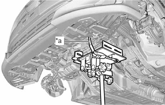
| *a | Lashing Belt |
Using a transmission jack, support the manual transaxle assembly.
- NOTICE:
- ·
Adjust the attachment of the transmission jack to securely support the manual transaxle assembly.
·Using a lashing belt or a rope, secure the manual transaxle assembly to the transmission jack.
30300
5.INSTALL MANUAL TRANSAXLE ASSEMBLY
12372A
6.INSTALL ENGINE MOUNTING INSULATOR LH
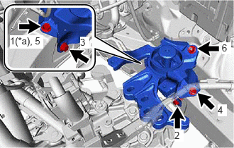
| *a | Temporarily Tighten |
Install the 4 bolts and nut in the order shown in the illustration.
- Torque:
- 42 N*m (428 kgf*cm, 31 ft.*lbf)
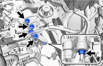
Install the 4 bolts and nut in the order shown in the illustration.
- Torque:
- Bolt : 42 N*m (428 kgf*cm, 31 ft.*lbf)
- Nut : 20 N*m (204 kgf*cm, 15 ft.*lbf)
Engage the clamp to connect the engine wire to the engine mounting insulator LH.
43409E
7.INSTALL DRIVE SHAFT HEAT INSULATOR SUB-ASSEMBLY
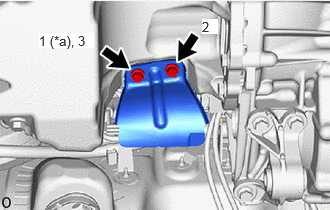
| *a | Temporarily Tighten |
Install the drive shaft heat insulator sub-assembly to the engine assembly with the 2 bolts in the order shown in the illustration.
- Torque:
- 23.5 N*m (240 kgf*cm, 17 ft.*lbf)
12364B
8.INSTALL NO. 2 ENGINE MOVING CONTROL ROD
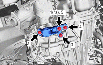
| *a | Temporarily Tighten |
Install the No. 2 engine moving control rod to the manual transmission case with the 4 bolts in the order shown in the illustration.
- Torque:
- 44 N*m (449 kgf*cm, 32 ft.*lbf)
51201
9.INSTALL FRONT SUSPENSION CROSSMEMBER SUB-ASSEMBLY
10.REMOVE ENGINE SUPPORT BRIDGE
Remove SST from the vehicle body.
- NOTICE:
-
Prevent SST from contacting the vehicle body or windshield glass.
Install the No. 3 radiator hose to the fan shroud with the 2 bolts.
Connect the inlet hose to the vehicle body with the clip.
11.REMOVE ENGINE HANGERS
31470
12.INSTALL CLUTCH RELEASE CYLINDER ASSEMBLY
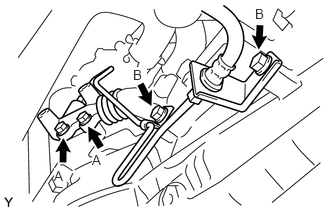
Install the clutch release cylinder assembly to the manual transaxle assembly with the 4 bolts.
- Torque:
- Bolt A : 13.8 N*m (141 kgf*cm, 10 ft.*lbf)
- Bolt B : 12 N*m (122 kgf*cm, 9 ft.*lbf)
31461
13.INSTALL RELEASE CYLINDER HEAT INSULATOR
Install the release cylinder heat insulator to the clutch release cylinder assembly with the 2 bolts.
- Torque:
- 11.8 N*m (120 kgf*cm, 9 ft.*lbf)
33820B
14.CONNECT TRANSMISSION CONTROL CABLE ASSEMBLY
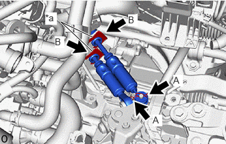
| *a | Paint Mark |
Install the transmission control cable assembly to the control cable bracket assembly with 2 new clips (B).
- NOTICE:
-
Make sure that the paint marks on the transmission control cable assembly are aligned with the slits in the control cable bracket assembly before installing the clips.
Connect the transmission control cable assembly to the manual transaxle assembly with the 2 clips (A).
82121
15.INSTALL ENGINE WIRE
Install the engine wire protector with the 2 bolts.
- Torque:
- 20 N*m (204 kgf*cm, 15 ft.*lbf)
Install the engine wire with the bolt.
- Torque:
- 10 N*m (102 kgf*cm, 7 ft.*lbf)
w/ Stop and Start System:
Connect the newutral position switch connector.
Connect the back-up light switch assembly connector.
Engage the 2 clamps.
17410
16.INSTALL FRONT EXHAUST PIPE ASSEMBLY
57543C
17.INSTALL CENTER NO. 1 FLOOR BRACE (w/ Brace)
74404A
18.INSTALL BATTERY CLAMP SUB-ASSEMBLY
89661
19.INSTALL ECM
17701
20.INSTALL AIR CLEANER CASE SUB-ASSEMBLY
17801
21.INSTALL AIR CLEANER FILTER ELEMENT SUB-ASSEMBLY
22.INSTALL AIR CLEANER CAP WITH AIR CLEANER HOSE
55701J
23.INSTALL OUTER COWL TOP PANEL SUB-ASSEMBLY (for LHD)
55701J
24.INSTALL OUTER COWL TOP PANEL SUB-ASSEMBLY (for RHD)
55734A
25.INSTALL WATER GUARD PLATE RH (for LHD)
55735A
26.INSTALL WATER GUARD PLATE LH (for RHD)
55815E
27.INSTALL FRONT NO. 1 VENTILATOR SEAL (for LHD)
55815E
28.INSTALL FRONT NO. 1 VENTILATOR SEAL (for RHD)
29.INSTALL WINDSHIELD WIPER MOTOR AND LINK ASSEMBLY
30.CONNECT CABLE TO NEGATIVE BATTERY TERMINAL
33820B
31.ADJUST TRANSMISSION CONTROL CABLE ASSEMBLY
32.BLEED CLUTCH LINE
51442C
33.INSTALL ENGINE UNDER COVER LH
51441C
34.INSTALL ENGINE UNDER COVER RH
51451A
35.INSTALL CENTER ENGINE UNDER COVER
36. INITIALIZATION AFTER RECONNECTING BATTERY TERMINAL
Click hereGeneral>SETUP>WHEN DISCONNECTING OR RECONNECTING BATTERY TERMINAL>WORK PROCEDURE
- HINT:
-
When disconnecting and reconnecting the battery, there is an automatic learning function that completes learning when the respective system is used.
-
Click hereGeneral>SETUP>WHEN DISCONNECTING OR RECONNECTING BATTERY TERMINAL>AUTOMATIC LEARNING CHART