CRUISE CONTROL LANE TRACING ASSIST SYSTEM Steering Pad Switch Circuit
DESCRIPTION
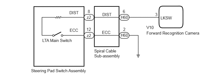
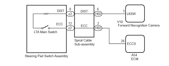
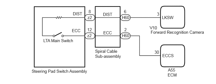
The forward recognition camera receives LTA main switch signals from the steering pad switch assembly.
WIRING DIAGRAM
for M15A-FXE
for M15A-FKS
for 1KR-FE
CAUTION / NOTICE / HINT
- NOTICE:
- ·
When replacing the forward recognition camera, always replace it with a new one. If a forward recognition camera which was installed to another vehicle is used, the information stored in the forward recognition camera will not match the information from the vehicle and a DTC may be stored.
·When the forward recognition camera is replaced with a new one or the windshield glass is replaced or removed/installed, make sure to read Before Starting Adjustment, then perform optical axis alignment for the forward recognition camera and clear the vehicle control history for each system.
- HINT:
-
Forward recognition camera axis alignment can be performed by using either One Time Recognition, Sequential Recognition or Driving Adjustment.
-
One time recognition: Click hereEngine / Hybrid System>CRUISE CONTROL>FRONT CAMERA>TARGET ADJUSTMENT(ONE TIME RECOGNITION)
-
Sequential recognition: Click hereEngine / Hybrid System>CRUISE CONTROL>FRONT CAMERA>TARGET ADJUSTMENT(SEQUENTIAL RECOGNITION)
-
Driving Adjustment: Click hereEngine / Hybrid System>CRUISE CONTROL>FRONT CAMERA>DRIVING ADJUSTMENT
·During the steering pad switch assembly check, check the precautions for the airbag system since the horn button assembly is removed during servicing. (installation/removal of parts, checks, replacement, etc.)
Click hereVehicle Interior>SUPPLEMENTAL RESTRAINT SYSTEMS>AIRBAG SYSTEM>PRECAUTION
PROCEDURE
Read the Data List according to the display on the GTS.
- Chassis > Lane Control > Data List
-
Tester Display Measurement Item Range Normal Condition Diagnostic Note LDA Control Whether lane tracing assist system control is permitted or not Prohibit or Permit Prohibit: Lane tracing assist system control not possible
Permit: Lane tracing assist system control possible-
- Chassis > Lane Control > Data List
-
Tester Display LDA Control - 50003 418 3
- Result:
Result Proceed to Data List value changes when LTA Main Switch is operated A Data List value does not change when LTA Main Switch is operated B
A
B
OK
NG
Click hereVehicle Interior>SUPPLEMENTAL RESTRAINT SYSTEMS>SPIRAL CABLE>INSPECTION
- Result:
Proceed to OK NG
OK
NG
Disconnect the H60 spiral cable sub-assembly connector.
Disconnect the V10 forward recognition camera connector.
Measure the resistance according to the value(s) in the table below.
- Standard Resistance:
Tester Connection Condition Specified Condition H60-6 (DIST) - V10-3 (LKSW) Always Below 1 Ω H60-6 (DIST) or V10-3 (LKSW) - Body ground Always 10 kΩ or higher
- Result:
Proceed to OK NG
OK
NG
Check vehicle condition.
- Result:
Result Proceed to for HV Model A for Gasoline Model B
A
B
Disconnect the H60 spiral cable sub-assembly connector.
Measure the resistance according to the value(s) in the table below.
- Standard Resistance:
Tester Connection Condition Specified Condition H60-2 (ECC) - Body ground Always Below 1 Ω
- Result:
Proceed to OK NG
OK
NG
Choose the model to be inspected.
- Result:
Result Proceed to for M15A-FKS A for 1KR-FE B
A
B
Disconnect the H60 spiral cable sub-assembly connector.
Disconnect the A54 ECM connector.
Measure the resistance according to the value(s) in the table below.
- Standard Resistance:
Tester Connection Condition Specified Condition H60-2 (ECC) - A54-28 (ECCS) Always Below 1 Ω H60-2 (ECC) or A54-28 (ECCS) - Body ground Always 10 kΩ or higher
- Result:
Proceed to OK NG
OK
NG
Disconnect the H60 spiral cable sub-assembly connector.
Disconnect the A55 ECM connector.
Measure the resistance according to the value(s) in the table below.
- Standard Resistance:
Tester Connection Condition Specified Condition H60-2 (ECC) - A55-30 (ECCS) Always Below 1 Ω H60-2 (ECC) or A55-30 (ECCS) - Body ground Always 10 kΩ or higher
- Result:
Proceed to OK NG
OK
NG