EXTERIOR PANELS / TRIM FRONT BUMPER(for 3 Door) REASSEMBLY
PROCEDURE

 52618
1.INSTALL FRONT BUMPER LOWER ABSORBER
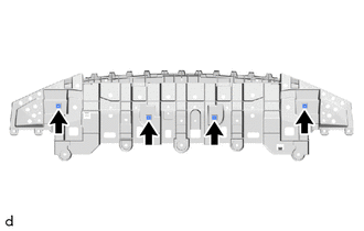
Install the 4 grommets.
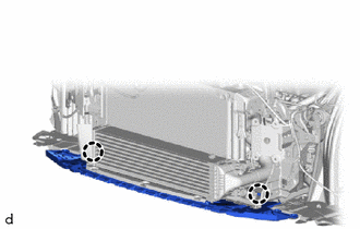
Engage the claws to install the front bumper lower absorber.
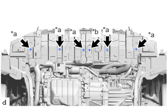
| *a | screw |
| *b | clip |
Install the clip and 5 screws.
51410
2.INSTALL NO. 1 ENGINE UNDER COVER ASSEMBLY
57014C
3.INSTALL FRONT SIDE MEMBER BRACKET SUB-ASSEMBLY LH
If install a new front side member bracket sub-assembly LH:
Temporarily install the front side member bracket sub-assembly LH with the 5 bolts until the "reference value" and " point-to-point distance" are aligned.
Vehicle Exterior > BODY PANEL > RADIATOR SUPPORT(for 3 Door) > REFERENCE VALUE
Vehicle Exterior > BODY DIMENSIONS > ENGINE COMPARTMENT REFERENCE VALUES(for 3 Door) > POINT-TO-POINT DISTANCE
If reusing the front side member bracket sub-assembly LH:
Temporarily install the front side member bracket sub-assembly LH with the 5 bolts until the matchmarks are aligned.
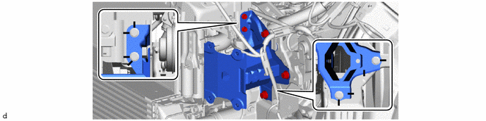
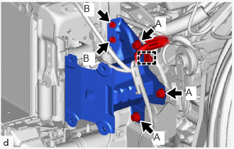
Tighten the 5 bolts.
- Torque:
- Bolt A : 40 N*m (408 kgf*cm, 30 ft.*lbf)
- Bolt B : 7.1 N*m (72 kgf*cm, 63 in.*lbf)
Engage the clamp.
57013D
4.INSTALL FRONT SIDE MEMBER BRACKET SUB-ASSEMBLY RH
If install a new front side member bracket sub-assembly RH:
Temporarily install the front side member bracket sub-assembly RH with the 5 bolts until the "reference value" and " point-to-point distance" are aligned.
Vehicle Exterior > BODY PANEL > RADIATOR SUPPORT(for 3 Door) > REFERENCE VALUE
Vehicle Exterior > BODY DIMENSIONS > ENGINE COMPARTMENT REFERENCE VALUES(for 3 Door) > POINT-TO-POINT DISTANCE
If reusing the front side member bracket sub-assembly RH:
Temporarily install the front side member bracket sub-assembly RH with the 5 bolts until the matchmarks are aligned.
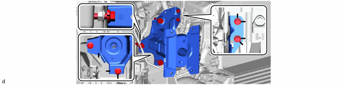
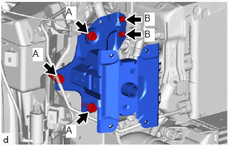
Tighten the 5 bolts.
- Torque:
- Bolt A : 40 N*m (408 kgf*cm, 30 ft.*lbf)
- Bolt B : 7.1 N*m (72 kgf*cm, 63 in.*lbf)
16595D
5.INSTALL NO. 1 RADIATOR AIR GUIDE LH
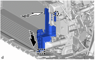

|
Install in this Direction (1) |

|
Install in this Direction (2) |
Engage the guide and claw to Install the No. 1 radiator air guide LH as shown in the illustration.
16593B
6.INSTALL NO. 1 RADIATOR AIR GUIDE RH
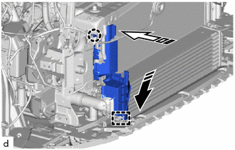
|
|
Install in this Direction (1) |
|
|
Install in this Direction (2) |
Engage the guide and claw to Install the No. 1 radiator air guide RH as shown in the illustration.
16695A
7.INSTALL FRONT RADIATOR SIDE AIR GUIDE PLATE LH
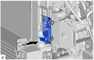
|
|
Install in this Direction |
Engage the claws to install the front radiator side air guide plate LH as shown in the illustration.
16691A
8.INSTALL FRONT RADIATOR SIDE AIR GUIDE PLATE RH
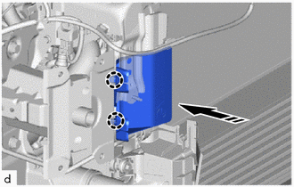
|
|
Install in this Direction |
Engage the claws to install the front radiator side air guide plate RH as shown in the illustration.
52131A
9.INSTALL FRONT BUMPER REINFORCEMENT
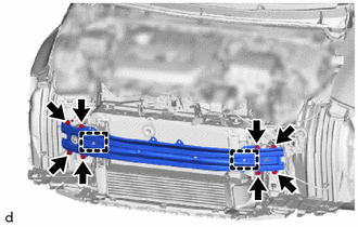
Engage the guides to install the front bumper reinforcement with 8 bolts.
- Torque:
- 67 N*m (683 kgf*cm, 49 ft.*lbf)
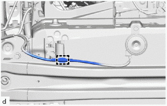
Engage the wire harness clamps.
53288A
10.INSTALL COOL AIR INTAKE DUCT
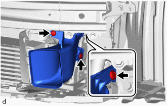
Install the cool air intake duct with 3 clips.
88790B
11.INSTALL THERMISTOR ASSEMBLY
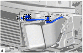
Engage the clamps to install the thermistor assembly.
52611
12.INSTALL FRONT BUMPER ENERGY ABSORBER
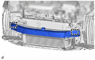
Engage the guides to install the front bumper energy absorber.
16681A
13.INSTALL RADIATOR UPPER AIR GUIDE PLATE
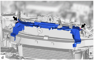
Install the radiator upper air guide plate with 2 clips.
52536
14.INSTALL FRONT BUMPER SIDE RETAINER LH
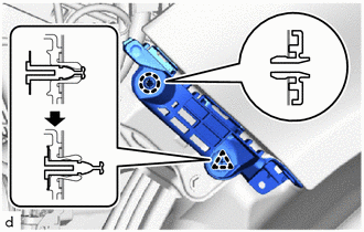
Engage the claw and clip to install the front bumper side retainer LH as shown in the illustration.
52535
15.INSTALL FRONT BUMPER SIDE RETAINER RH
- HINT:
-
Use the same procedure as for the LH side.
16.INSTALL HEADLIGHT ASSEMBLY LH
17.INSTALL HEADLIGHT ASSEMBLY RH
- HINT:
-
Use the same procedure as for the LH side.
75310A
18.INSTALL RADIATOR GRILLE EMBLEM ASSEMBLY
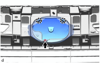
Engage the claws to install the radiator grille emblem assembly.
Install the screw.
53124F
19.INSTALL RADIATOR GRILLE SIDE MOULDING LH
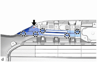
Engage the claws to install the radiator grille side moulding LH.
Install the screw.
53123G
20.INSTALL RADIATOR GRILLE SIDE MOULDING RH
- HINT:
-
Use the same procedure as for the LH side.
53102B
21.INSTALL LOWER RADIATOR GRILLE SUB-ASSEMBLY
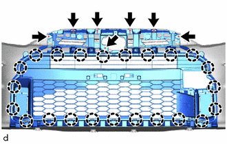
Engage the claws to install the lower radiator grille sub-assembly.
Install the 4 clips and 3 screws.
52114B
22.INSTALL FRONT BUMPER EXTENSION MOUNTING BRACKET
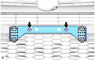
Engage the guides and claws to install the front bumper extension mounting bracket.
Install the 2 screws.
53395E
23.INSTALL HOOD TO FRONT END PANEL SEAL
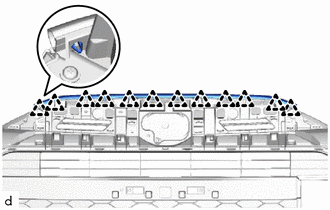
Engage the clips to install the hood to front end panel seal.
52127C
24.INSTALL FRONT BUMPER HOLE COVER
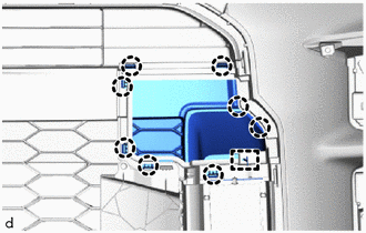
Engage the hook to install the front bumper hole cover.
Engage the claws.
81482C
25.INSTALL FOG LIGHT COVER LH
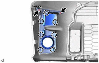
Engage the guide and claws to install the fog light cover LH.
Install the 2 screws.
81481E
26.INSTALL FOG LIGHT COVER RH
- HINT:
-
Use the same procedure as for the LH side.
81220
27.INSTALL FOG LIGHT ASSEMBLY LH
81210A
28.INSTALL FOG LIGHT ASSEMBLY RH
- HINT:
-
Use the same procedure as for the LH side.
82113
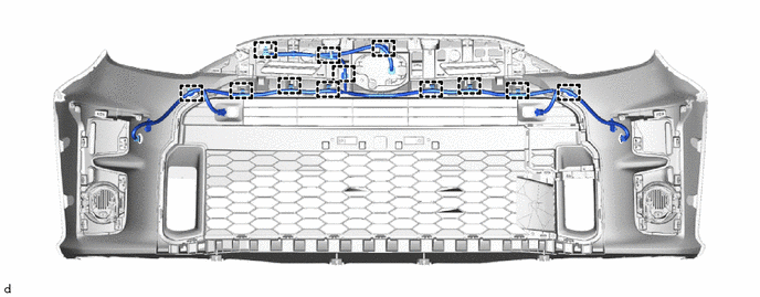
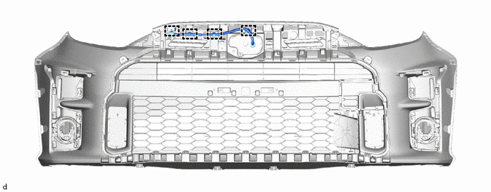
29.INSTALL NO. 3 ENGINE ROOM WIRE (w/ Wire Harness)
w/ Parking Support Brake System:
Engage the clamps to install the No. 3 engine room wire.
w/o Parking Support Brake System:
Engage the clamps to install the No. 3 engine room wire.
88211B
30.INSTALL MILLIMETER WAVE RADAR SENSOR ASSEMBLY (w/ Toyota Safety Sense 2)
89347B
31.INSTALL FRONT CORNER ULTRASONIC SENSOR RETAINER (w/ Parking Support Brake System)
89341L
32.INSTALL FRONT CENTER ULTRASONIC SENSOR (w/ Parking Support Brake System)
89341K
33.INSTALL FRONT CORNER ULTRASONIC SENSOR (w/ Parking Support Brake System)
89348N
34.INSTALL NO. 1 ULTRASONIC SENSOR CLIP (w/ Parking Support Brake System)